In the drive to reduce cost and space, monolithic DC-DC converters are a good solution for many high-volume applications, but they can’t be used in designs that require electrical isolation of the power supply input from the output. Medical devices are a good example.
Typically, board mounted isolated supplies can be used instead, but these rely upon a transformer to achieve the required electrical isolation, thereby lowering efficiency and increasing the cost, size, and weight of the solution. The transformer also introduces variability in the DC-DC converter’s performance and makes high-volume automated assembly difficult.
To address many of these challenges, designers can turn to isolated DC-DC converter modules that have the transformer embedded into the converter’s substrate.
This article explains the circumstances that require the use of isolated DC-DC converters. It then introduces example solutions from Murata Electronics and shows how they can be used to achieve isolation without the major design compromises typically associated with transformer-based isolated DC-DC converters. The article also describes how the converter’s package meets the need of high-level, automated surface mount assembly, and shows how to design the isolated DC-DC converters into products with minimal voltage and current ripple and reduced electromagnetic interference (EMI).
When to use an isolated converter
In a conventional DC-DC converter, a single regulator circuit allows current to flow directly from input to output. This reduces complexity, size, and price. But there are many applications that require galvanic isolation (from now on referred to simply as “isolation”) to electrically separate the input and output sides of the device. For example, safety requirements may dictate the use of an isolated DC-DC converter—using a transformer (or in some cases coupled inductors) to transfer voltage and current across the gap between the input and output sides—particularly if the input side is connected to voltages that are high enough to endanger humans. Isolated DC-DC converters are also useful for breaking up ground loops, thus separating parts of a circuit that are sensitive to noise from the sources of that noise (Figure 1).
Figure 1: A basic non-isolated DC-DC converter (top) compared with an isolated version (bottom) using a transformer for galvanic isolation. (Image source: Digi-Key Electronics)
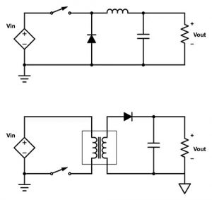 Another feature of an isolated DC-DC converter is a floating output. While such converters do supply a fixed voltage between the output terminals, they don’t feature a defined or fixed voltage relative to voltage levels in the circuits from which they’ve been isolated (i.e., they are “floating”). There is an option to connect an isolated DC-DC converter’s floating output to a circuit node on the output side to fix its voltage, which then enables the output to be shifted or inverted relative to another point situated in the output side circuit. Because of the separation of input and output circuits, the designer must ensure both circuits have their own ground references.
The datasheet for a given DC-DC converter typically lists its isolation voltage—the maximum that can be applied for a defined (short) time without current bridging the gap. In addition, the datasheet details the maximum operating voltage that can be continuously withstood without breaking the isolation.
Isolation does bring some trade-offs. First, isolated converters tend to be more expensive because the (typically custom) transformer is more expensive than the equivalent (off-the-shelf) inductor used in the non-isolated version. The higher the isolation required, the greater the cost.
Second, isolated DC-DC converters tend to be larger than non-isolated versions; the transformer is generally larger than the equivalent inductor and the inductor tends to operate at higher switching frequencies, further reducing its size compared with the transformer.
Third, the efficiency, regulation, and performance repeatability from component-to-component of isolated DC-DC converters tends to be inferior to non-isolated converters. The transformer introduces some inefficiencies compared with an inductor, and the isolation barrier prevents the output from being directly sensed and tightly controlled for better regulation and transient performance. Because they are smaller, non-isolated DC-DC converters can be placed close to the load to reduce transmission line effects and further nudge up efficiency. Also, since the transformer in isolated converters is typically a custom manufactured device, no two devices provide exactly the same output.
Finally, that transformer can also get in the way of an efficient high-volume assembly process. The profile of the isolated DC-DC converter with a transformer makes it unsuited for automated assembly, dictating that it has to be added to the PCB by hand.
Isolated DC-DC converter selection
If the designer’s application demands isolation for safety or other reasons, then the trade-offs previously described have to be accommodated. Diligent component research can reveal some newer solutions that have been designed to minimize the impact of the design compromises.
For example, Murata has recently introduced its NXE (Figure 2) and NXJ2 Series isolated DC-DC converters. These are designed to address some of the traditional challenges presented by isolated DC-DC converters.
Figure 2: Murata’s NXJ2 and NXE (shown) isolated DC-DC converters include a transformer embedded within the components’ substrate to reduce the size of the product. (Image source: Murata Electronics)
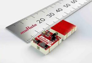 The NXE Series offer up to 2 watts with 5 and 12 volt input options and 5, 12, and 15 volt output options. Input and output current vary with voltage, but ranges from 542 milliamps (mA) input/400 mA output for the 5/5 volt product to 205/133 mA for the 12/15 volt product. The product range features switching frequencies from 100 to 130 kilohertz (kHz) depending on the model.
Similarly, the NXJ2 Series is a 2 watt design with 5, 12, and 24 volt input options and 5, 12, and 15 volt output options. Input and output current ranges from 550 mA input/400 mA output for the 5/5 volt product to 105/133 mA for the 24/15 volt product. The products feature switching frequencies from 95 to 140 kHz.
The Murata isolated DC-DC converters address the challenges of automated manufacture by embedding the transformer into the substrate of the device. The transformer is formed from alternate layers of FR4—the glass-reinforced epoxy laminate often used as the base for printed circuit boards—and copper to create the windings around the embedded core. The embedded transformer construction is claimed to aid heat dissipation and enhance performance repeatability between components.
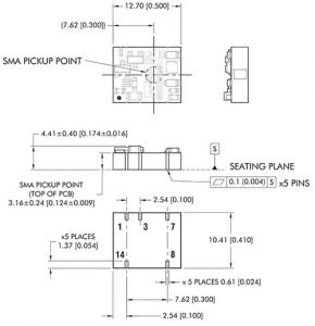
The result is a low profile (under 4.5 millimeters (mm)), compact (15.9 x 11.5 mm for the 5 and 12 volt versions and 16 by 14.5 mm for the 24 volt version) package suitable for tape and reel packaging, able to be picked up by the vacuum nozzle of an automated placement machine (Figure 3).
Figure 3: The NXE isolated DC-DC converters are housed in a compact package that can be tape and reel fed and placed on the pc board by automated assembly equipment. (Image source: Murata Electronics)
 The embedded transformer design results in good electrical performance compared with other isolated designs. Isolated DC-DC converters typically operate in the 55 to 85% efficiency range when under full load. The NXE Series and NXJ2 Series are around 72% efficient under 100% load with a 5 volt output, rising to 76% efficient for a 15 volt output, and 78% efficient for a 24 volt output.
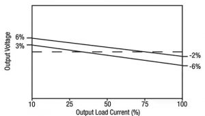
Isolated DC-DC converters generally lack the precise regulation typical of non-isolated products because they don’t have an electrical feedback loop between output and input. For the NXE series, the line regulation is 1.15 %/% and load regulation is between 7 and 11%. The NXJ2’s line regulation is 1 %/% typ for 24 volt input and 1.1 %/% typ for all other input types. The accuracy of the voltage setpoint depends on output load current and the NXE or NXJ2 device selected. For example, the NXE2S1215MC 12 volt input/15 volt output solution exhibits a -2 to -6% variation against set point at full output load current (Figure 4).
Figure 4: Isolated DC-DC converters lack the precise regulation typical of non-isolated DC-DC converters. The accuracy of the voltage setpoint varies depending on output load current. The example here shows the output voltage accuracy against the setpoint for different loads for the NXE2S1215MC, Murata’s 12 volt input/15 volt output isolated DC-DC converter. (Image source: Murata Electronics)
 Understanding the specifications
Electrical separation of the input from the output is often a regulatory requirement, making it important that the engineer be clear what regulations demand for a given design. This can be difficult because the information can be confusing.
For example, regulatory standards separately specify the isolation required for a component and isolation required for an end product—and it is different for each. So, for example, the spec sheet for a component might state the device can withstand an isolation test voltage of 2.5 to 5 kilovolts AC and that it adheres to product standard IEC 60950-1, when what is more important to the designer is that the isolator working voltage is, for example, 150 to 600 volts AC and that it adheres to component standard IEC 60747-5-5.
Care should also be taken regarding the terminology used to describe the isolation levels. “Basic” is a single layer of isolation and “Double” is two layers; “Reinforced” is a single insulation system that is equivalent to Double. The standards assume a single fault can occur in one layer of insulation so a product with a second insulation layer will still offer protection. Importantly, when a component is defined as “Basic” in a component standard, it is classed as inadequate for safety protection.
Another important aspect of the component’s isolation performance is its clearance and creepage. Clearance is the shortest distance between two component circuits through air, while creepage is the shortest distance across a surface.
The best way a designer can be sure of isolator performance is to verify that an isolator has VDE and Underwriters Laboratory (UL) Certifications and obtain a copy of the actual certificates from the isolator manufacturer.
In the case of the NXE and NXJ2 series, where FR4 provides the insolation barrier between the converter’s primary and secondary windings, every component has been tested at 3 kilovolts DC for one second with samples qualification tested at 3 kilovolts DC for one minute. Insulation resistance is measured at 10 gigaohms (GΩ) at a test voltage of 1 kilovolt DC.
The NXE and NXJ2 series is recognized by UL to ANSI/AAMI ES60601-1 and provides one MOOP (Means of Operator Protection) based upon a working voltage of 250 volts rms max, between primary and secondary coils. UL also recognizes the DC-DC converters against UL 60950 for reinforced insulation to a working voltage of 125 volts rms. Creepage for the devices is 2.5 mm and clearance is 2 mm.
Decreasing output ripple and EMC
Switching voltage convertes always carry design challenges related to voltage and current ripple generated by the switching elements. Isolated DC-DC converters are no exception.
Without output filter circuits, the typical output ripple from the NXE DC-DC converters is around 55 millivolts (mV) peak-to-peak (p-p) rising to a maximum of 85 mVp-p. The corresponding numbers for the NXJ2 Series are 70 mVp-p and 170 mVp-p. While these values are acceptable for many applications, others demand a more stable output.
The output filter circuit shown in Figure 5 can be used to dramatically lower the output current and voltage ripple. The values of inductor (L) and capacitor (C) vary depending on the input and output voltages of the DC-DC converter; but for example, Murata’s NXE2S1205MC (12 volt input/5 volt output) product requires an inductor of 22 microhenries (µH) and a capacitor of 10 microfarads (µF). The effect of the output filter circuit is to lower output voltage and current ripple to a maximum of 5 mVp-p.
Figure 5: This simple output filter circuit with appropriate L and C values can reduce the isolated DC-DC converter output current and voltage ripple by an order of magnitude. (Image source: Murata Electronics)
 For best results, the capacitor’s equivalent series resistance (ESR) should be as low as possible, and the voltage rating should be at least twice the rated output voltage of the isolated DC-DC converter. For the inductor, the rated current should not be less than that of the output of the DC-DC converter. At the rated current, the DC resistance of the inductor should be such that the voltage drop across the inductor is less than 2 percent of the rated voltage of the DC-DC converter.
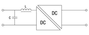
An input filter circuit can be added to the NXE and NXJ2 Series to dampen EMI as shown in Figure 6. Again, the values of L and C vary depending on the input and output voltages of the DC-DC converter; but for example, Murata’s NXE2S1215MC (12 volt input/15 volt output) product requires an inductor of 22 µH and a capacitor of 3.3 µF.
Figure 6: This simple input filter circuit with appropriate L and C values can reduce the EMI emissions of the isolated DC-DC converter to below those required to meet EN 55022 limits. (Image source: Murata Electronics)
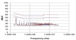
 As shown in Figure 7, the effect of the filtering enables the Murata isolated DC-DC converters to meet the EN 55022 Curve B Quasi-Peak EMC limit. An EMI radiating device must better these limits to meet the EU’s EMC Directive 2014.
Figure 7: The effect of the input filter circuit shown in Figure 6 is to lower the isolated DC-DC converter (NXE2S1215MC, in this case) EMI emissions to below the limits mandated by the EU’s EMC Directive. (Image source: Murata Electronics)
 For more on filter circuit design for DC-DC converters, see the Digi-Key technical article, Capacitor Selection is Key to Good Voltage Regulator Design.
Conclusion
Isolated DC-DC converters perform a vital role when regulations or safety considerations demand electrical separation of input and output voltages. However, isolation using a transformer can bring design compromises—notably cost, size, performance variability, and assembly challenges.
Engineers need to be aware of these compromises and design products accordingly. For example, isolated DC-DC converters generally lack the feedback loop that allows for the precise regulation of non-isolated products, so output voltages can vary more widely with load from the set point than with the latter components.
As shown, there are DC-DC solutions that instead of using an expensive and bulky board mounted transformer, use alternating layers of FR4 and copper to build up a transformer embedded in the converter’s substrate. The result is a less expensive, compact device that shows better component-to-component electrical performance repeatability and can be handled by automated placement machinery. These isolated DC-DC converters also meet relevant standards for high-voltage isolation and insulation testing.

