While developer kits have already been available for designing products around magnetic sensors, they were fairly expensive at 500 Euro with the required magnet/sensor not even included. Against this background, Infineon is now rolling out various design kits at about 20 Euro each for an easy evaluation of its sensors as part of its Product2System approach. It is important for developers to determine, if the sensors selected meet the performance requirements right from the start of the sensor design. What they need is a faster and simpler performance check. The next step is to define the operating range in relation to the different design parameters. The magnets required also need to be available. The final step is to ensure the sensors can actually be manufactured.

Various evaluation kits such as “3D Magnetic Sensor 2Go”, “Current Sensor 2Go” and “Speed Sensor 2Go” are intended to let developers see how the sensors work in the respective application at an early stage in the design phase, and help them get to the design phase easily. The evaluation kits currently support 3D “TLV493D” magnet sensors for three-dimensional position detection, the “TLI4970” current sensor, and the “TLE4922” speed sensor.
Precise three-dimensional sensing
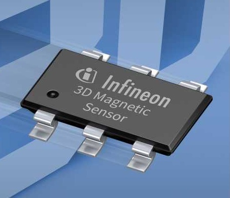
The TLV493D 3D magnet sensor (Figure 1) measures a magnetic field in x-, y- and z-direction and detects three-dimensional, linear and rotating movements. This means it is ideal for a wide range of automotive, industrial and consumer applications.
Possible applications include joysticks and control elements such as household appliances and multi functional buttons as well as tamper protection for current meters or other applications where precise position measurements and/or low current draw are required. For example, the TLV493D-A1B6 is housed in a TSOP-6-package with the dimensions 2.9 mm × 1.6 mm.
This is made possible by the integration of both vertical and horizontal Hall plates on the sensor chip. The vertical Hall plates detect the planar x direction and y field components. The horizontal Hall plate detects the vertical z field component.
Technologies such as the power-saving oscillator allowed Infineon to reduce the current draw of the sensor to only a few microamperes. The sensor has a digital output via a fast two-wire I²C-based interface, enabling it to use the bus mode and making bidirectional communication between sensor and microcontroller possible.
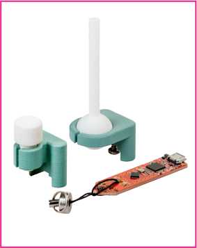
The “3D Magnetic Sensor 2Go” Design Kit (Figure 2) provides an evaluation board equipped with a 3D magnet sensor and an XMC1000-type microcontroller with an ARM® Cortex®-M0 processor for designs incorporating this sensor. The kit features all the components and functions needed for efficient design support, including a debugger. An XMC4200 microcontroller is also available for debugging and for USB communication, Power and communication with the graphical user interface (GUI) are provided via a micro USB connector. The board also includes LEDs that display power supply and debugging status, as well as user-configurable LEDs, voltage controllers, reverse current diodes and ESD protection diodes. Using a pin header, it is also possible to connect an oscilloscope or an external microcontroller.
The package also includes a single magnet that can be placed manually. Infineon also provides magnet holders that can be mounted on the evaluation board. The image shows two designs – a joystick and a rotary knob (Figure 2).
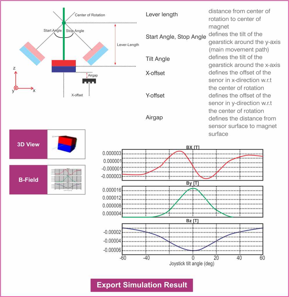
A special online design tool supports typical applications of the sensor – angle/linear position measurement and joysticks (Figure 3). For each of the three applications, the tool provides pre-defined or user-customized magnets. The online simulation tool can be used to define magnets, the movement of the magnets and the position of the sensor. The sensor detects the movement and supplies a corresponding signal to the output. Users can select movements for angle measurements such as the magnet’s rotation, linear movements as well as movements specific to the joystick application, including 3D magnet movements. The tool automatically calculates the three magnetic field positions for each sensor position. This calculation is based on the sensor configuration defined by the user, taking the mounting tolerances for the sensor and the magnets into account.
The software package of the kit also includes a graphical user interface for a PC as well as firmware, which is stored in the flash memory for communication with the 3D sensor on the microcontroller. The Segger J-Link USB Driver connects a PC with the evaluation board.
With the 3D Magnetic Sensor 2GO, various operating modes such as the update rate for the measurements in the x-, y- and z-direction are adjustable. This means current draw is adjustable as well.
Measuring current made easy
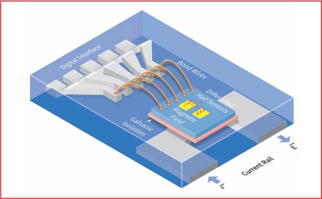
The TLI4970 is a high-precision current sensor based on Infineon’s Hall effect technology, with a galvanic separation between the busbar as the primary side and the interface to the microcontroller as the secondary side (Figure 4). The “coreless” concept without a magnet flux concentrator as in open-loop
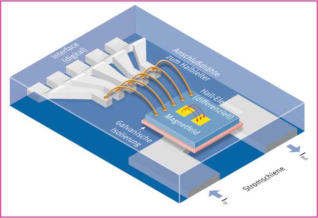
configurations makes it possible to significantly reduce the size of the component. This structure also avoids any hysteresis effects. The fully digital sensor solution requires no external calibration or additional components such as AD converters, operational amplifiers, or voltage references. This simplifies the design and reduces both PCB space and cost.
The chip in the small QFN-like SMD package (7.0 mm x 7.0 mm) provides a high accuracy of 1.6% over temperature and lifetime as well as a maximum offset error of 75 mA. The TLI4970 has overcurrent detection with configurable thresholds as well as programmable filters. The typical current draw is 12 mA.
The differential measuring principle implemented in the TLI4970 protects against interference from external magnetic fields and the sensor has separate structures for measuring temperature and mechanical stress. Since these two parameters are measured separately during operation, the component can be offset permanently and effectively. This is the basis for long-term stable measurements and thus for efficient, reliable and cost-optimized converters or drives.
The TLI4970 can measure alternating and direct currents up to ± 50 A in applications such as solar converters, power supplies with power factor correction (PFC), chargers or electrical drives. The contactless measuring technique does not cause any additional losses, making it ideal for low-power designs (Rp<0.6 mΩ). Thanks to the integrated stray field suppression, the sensor is extremely insensitive to external magnetic fields.
In addition to accurate current measurement, this also provides efficient protection e.g. for power amplifiers. For example, external short circuits can trigger critical over currents. To keep the latency extremely short, the TLI4970 provides a parallel signal path. This means that the sensor typically only needs 1.8 µs for detecting errors. In order to optimally adapt the overcurrent threshold to the requirements of the application, the system developer can program both the current value and the downstream filtering in the sensor. Since the busbar is integrated into the SMD packaging, the sensor can be fully calibrated when it is delivered.
The TLI4970 is one of the first current sensors to transmit the measured values via the 16-bit digital SPI interface. For example, it integrates differential amplifiers, filters and signal processing and makes it possible to measure operating voltages of up to 600 V and test voltages of up to 3.600 V while providing galvanic insulation.
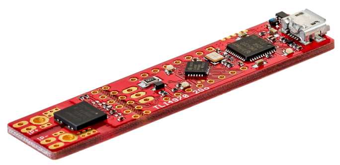
An easy-to-use design kit is available for the TLI4970 current sensor, the Current Sensor 2GO.
Fast speed measurement
The Hall sensor TLE4922 detects the motion and position of ferromagnetic structures by measuring changes in the magnetic field. Such a structure may be a magnetic encoder wheel or a ferromagnetic gear wheel. The TLE4922 can be used in a back-bias configuration with a simple, cost-efficient magnet while providing high air gap performance and switching accuracy. The sensor is highly insensitive to vibration and air gap jumps. It can provide precise speed detection across the frequency range up to 8 kHz.
The TLE4922 is particularly suitable for a TIM (Twist Independent Mounting) configuration. It can therefore replace passive VR (variable reluctance) sensors in automotive or two-wheeler applications. It also has very good jitter behavior.
In addition, the sensor provides comprehensive protection features against short circuits, overtemperature and reverse voltage. Its good electromagnetic compatibility (EMC) and ESD robustness make it suitable for use in harsh environments. The sensor is available in a 4-pin SSO-4-1 package.
For applications based on the TLE4922, the easy-to-use Speed-Sensor-2GO kit is available (Figure 6). The kit consists of the sensor (TLE4922-XAN) and a back-bias magnet (ferrite magnet from Bomatec). Connecting PCs is easy using the USB connector. A GUI-based evaluation tool captures and displays digital and emulated analog data in the real application as a function of parameters such as air gap, temperature and frequency.
Using the TLE4922, the kit can be internally connected to either the module provided or other modules assembled by the customer. The kit can also be used as a mapping tool for magnetic field processing. The internal architecture corresponds to a linear Hall sensor. With the TLE4922, developers can evaluate module positioning with respect to a gear wheel.

