A number of companies are contemplating entering the fast-growing automotive IC market. However, there are significant barriers to entry and one of those is compliance to ISO26262 which governs how automotive ICs must be developed to be demonstrably safe. Automotive verification experts Test and Verification Solutions recently organized a DVClub on this subject and in this paper T&VS CEO Mike Bartley considers a few of the major ISO26262 verification challenges: risk analysis, requirements traceability, and fault analysis.

Automotive Safety Integrity Levels (ASIL)
Any new automotive IC development must start with identifying the appropriate safety level. For this we identify and classify the risks based on 3 factors: severity; exposure; and controllability.

The severity identifies the potential impact of any risk and the exposure identifies the probability. These two terms define our classic risk analysis, but we also need to consider how much control the driver has over the risk. For example, if the car decides to apply the brakes and there’re no override by the driver then that has very low controllability. From these three variables we determine the safety integrity level (QM represents standard quality management processes). The higher the ASIL then the more rigorous the development process needs to be (e.g. higher levels of coverage).
Where’s the Proof? – The Importance of Requirements Management
Turning to requirements we need to be able to trace stakeholder requirements through to their proof of implementation. The stake holder requirements include both Internal and external customers as well as functional and safety requirements. An example of the latter might be the ability to detect a lane change and alert the driver.


Proof of implementation typically involves mapping requirements to measurable verification goals such as coverage goals (structural and functional), tests (directed and random), assertions, etc. The goals will then need to be satisfied via verification tasks. Note that the mapping of requirements through the hierarchy is bi-directional so that every line of code and verification goal is associated with a requirement.
Getting Fault Analysis Right
Turning to fault analysis, we first consider how systems fail.
- Random failure: For example, a gate gets struck at zero or one or an external influence, such as an alpha particle, flips the value of a bit. Slightly paradoxically, using statistics we can predict the number of random failures. What we have to be able to do in our chips: is be able to detect those random failures and either recover from them or fail gracefully.
- Systematic failures: During the development process there is the potential to introduce errors at any stage. For example: not fully capturing the requirements; not correctly translating requirements into a specification, bugs in the code, or errors in the verification. In order to avoid and detect such systematic failures, we must follow well-managed development process which will deliver a number of pre-defined development artifacts such as requirements and specification documents, code reviews, test plans, etc.
- Systemic failure: These refer to failures in the culture and practices of the organization for example, a poor-quality management culture.
Based on the ASIL we need to demonstrate that our chip can detect a certain percentage of faults, with a higher percentage for a higher ASIL. In order to do this, we first select appropriate fault models, including both permanent faults such as stuck at and transient faults such as an external alpha particle. We then analyse the chip design (digital and analog) to identify all the potential faults based on the models and inject each fault into the design and then run a verification task (typically a simulation) that hits the fault. From that we can then check if the chip (or software running on the chip) detects the bug. The chip will apply a variety of detection techniques such as: ECC, lockstep designs that might have two CPUs running in parallel comparing their results, or software that runs DFT patterns multiple times a second. Of course, the chip would then take appropriate action (e.g. through an interrupt).
The Safety Verification Journey of an SoC
Automotive verification was covered in detail at a recent T&VS DVClub India event in Bangalore where Arif Mohammed, DV Manager at Texas Instruments presented a paper on “Safety Verification Journey of a SoC (MCU) from Specification to Certification”. In addition, Lokesh Babu Pundreeka, Technical Director in the System Verification Group at Cadence Design Systems considered if we are ready for the new set of verification challenges for automotive SoC’s.

Arif outlined the hardware components contributing to safety such as lock-step and BIST, parity and ECC before considering how the design and safety verification process can create safety collaterals such as the traceability and FMEDA (Qualitative, Quantitative, Fault injection) outlined earlier. He went on to identify potential functional failure modes applicable for a communication peripheral including message corruption, unintended repetition, incorrect sequence, unacceptable delay, message loss and incorrect addressing. Arif’s presentation identifies a number of challenges including huge fault lists, un-optimized workload (i.e. many tests), low functional coverage and fault coverage leading to long tool simulation times and suggested formal verification as an alternative approach.
Lokesh described how our knowledge and experience from consumer and mobile ASIC’s design and verification may not be enough to meet the requirements for Automotive SoC’s and how Cadence tools can help.
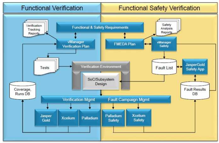
T&VS recently deployed the Cadence safety flow on an automotive IC development for a client starting with failure modes, effects, and diagnostic analysis (FMEDA). This is a systematic analysis technique to obtain subsystem / product level failure rates, failure modes and diagnostic capability as discussed above. The FMEDA produces an exhaustive list of all the safety requirements (along with their ASIL level) as well as a mechanism/processes to verify each safety requirement. Using the Cadence functional safety verification flow allows integrated fault campaign management across formal, simulation, & HW acceleration.
To know more about the next T&VS DVClub Europe meeting, click here.

