Even though ideal diode ICs can make a positive impact on many designs, engineers often forget about using them. Ideal diode ICs simply use a MOSFET to act like a diode, but deliver significantly reduced voltage drop and leakage.
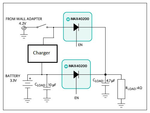
There are three primary applications for ideal diodes. One is simple reverse voltage protection for a battery-operated device. This is simply a diode in series from the battery to the application circuit. The second is as a diode OR for high-reliability redundant power supplies. Last is the same diode OR circuit, but for a selection circuit between an on-board rechargeable battery and a wall charger—just like your cell phone and many portable equipment have. Ideal diodes (such as the MAX16915) are also used for overvoltage protection on power inputs.
A designer could move from a standard diode to a Schottky diode in all three of the applications mentioned. That will be a big help with forward voltage drop with the voltage going from 1.1V for a standard diode to around 0.45V at a 1A forward current. However, an ideal diode, which are fairly inexpensive and also much smaller, will take you down to 85mV at that current. In addition, an ideal diode IC reduces power consumption, cuts voltage loss (important when coming from a low-voltage battery), and will consume less PC board area. Besides, they solve a big Schottky problem. Schottky diodes have a very high reverse leakage—around 1mA for the 1A device. This leakage is not good for primary batteries, in particular. An ideal diode typically has a reverse leakage of less than 1µA over temperature.
There are three ways to get ideal. Making your own is one option, using a driver IC for an external FET or a device with an integrated FET. Driving the FET, however, is not as easy as you might think. For a smooth current transfer from one path to the other without oscillation, it’s important that the drive circuit control the forward voltage drop across the MOSFET. If the power source fails or is shorted, a fast turn-off minimizes reverse current transients. Implemented correctly, an ideal diode can provide front-end protection against reverse battery conditions, overvoltage transients, and inrush current. Ideal diode controller ICs, using external FETs, are available with current ratings up to 5A and voltage rating to 80V.
Complete Ideal Diode
A great example of a complete ideal diode device is Maxim’s MAX40200, which operates from a supply voltage of 1.5V to 5.5V, handles up to 1A, and comes in a tiny 0.73mm square 4-bump WLP or a SOT23-5 package. It is thermally self-protecting and works over -40° to 125°C. When disabled, the MAX40200 blocks voltages up to 6V in either direction.
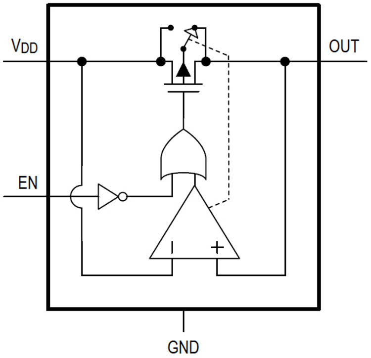
The functional diagram in Figure 1 shows a unique symbol for the internal FET. The p-channel FET has added circuitry to sense the MOSFET drain-to-source voltage and, in addition to driving the gate, keep the body diode reverse biased. One difference versus normal diodes is that this “ideal diode” is not suited for rectifying AC. In applications where the supply is an inductively coupled 60Hz AC, conventional diodes should be used for the rectification part of the circuitry. MAX40200 is designed to be used in applications to switch between different DC sources. The chip exhibits a regulated ~20mV voltage drop up to 100mA of forward current.
Above that, the forward drop increases to roughly 90mV at the maximum rated forward current of 1A. This small voltage drop will increase efficiency and significantly increase battery operation times. The IC’s dynamic response is detailed in an application note, “Static and Dynamic Behavior of the MAX40200 in a Diode ORing Application.” You can also test drive the part using the evaluation kit, MAX40200EVKIT. As an example, consider an AAA battery with 1Ah capacity at ~3V for two cells. If a Schottky diode drops 0.36V at 1A and our MAX40200 drops only 0.09V, the 0.27V difference yields 0.27Wh saved. So your device will run an extra quarter hour at the 1A maximum load.
The IC has a thermal shutdown temperature of about +154°C with 12°C hysteresis. If currents exceed ~500mA, be cognizant that your design doesn’t exceed this temperature. The thermal performance of the WLP package actually exceeds that of the SOT package.
IC to Protect Your System from Various Voltage Conditions
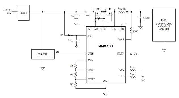
The MAX16141 ideal diode controller has a much different job than our first example. This chip provides system protection against reverse-current, overcurrent, input overvoltage and undervoltage, and over temperature conditions. It will cut off and isolate a faulty input supply. Its wide 3.5V to 36V operating voltage range and low 5μA (typ) shutdown current make the MAX16141 a good fit for automotive applications (by the way, the IC is also automotive qualified).
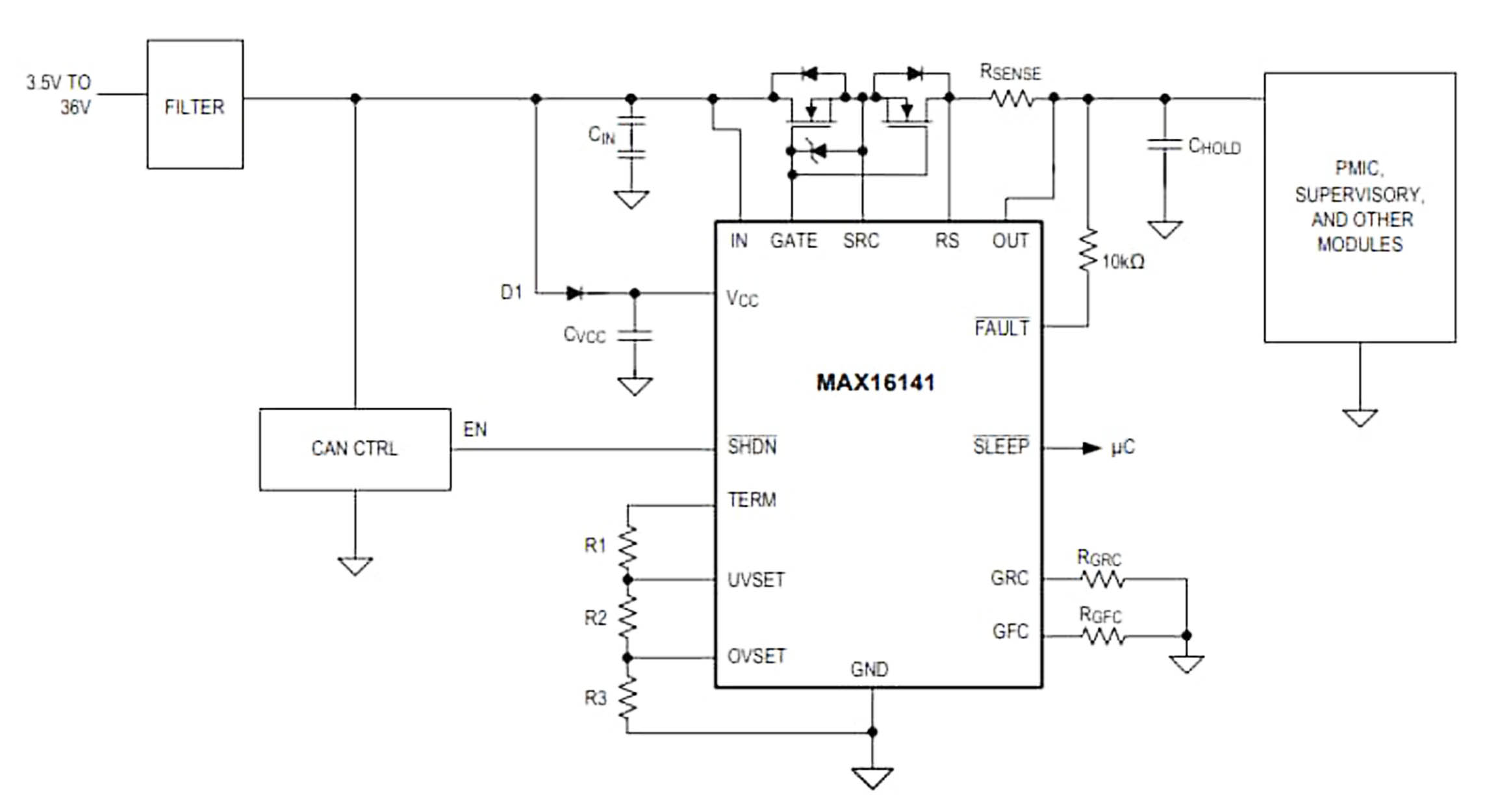
In the circuit in Figure 3, the IC’s charge pump drives the gate of back-to-back external nFETs to 9V above the source connection. A fast-acting comparator blocks reverse-current flow within 1μs (max) of the input falling below the output voltage. An external current-sense resistor between RS and OUT keeps an eye out for current overloads. Maximum current is adjustable and determined by your choice of FETs. OVSET and UVSET inputs provide set points for input overvoltage and undervoltage events. The MAX16141 is available in a 4 x 4 x 0.75mm, 16-pin TQFN package and operates over -40° to 125° C.
In summary, it’s quite clear that ideal diodes can provide benefits for many designs. They may be underused because, perhaps, no one seems to know quite where to put them. They also get classified differently, sometimes as amplifiers, other times as power management, and yet other times as circuit protection. Regardless, it does pay dividends for engineers to be aware of what these devices can deliver.


