Information on our surrounding environment can be obtained by sensing Automotive technologies to benefit our everyday lives: either to improve task efficiency, our safety, or purely for entertainment purposes. LiDAR is one such sensing technique that uses laser light to measure the distance to objects and can be used to create a 3D model of the surrounding environment. Each pixel in the image captured by the LiDAR system will have a depth associated with it. This allows for better object identification and removes any ambiguity that might be present in a 2D image obtained by an image sensor alone.
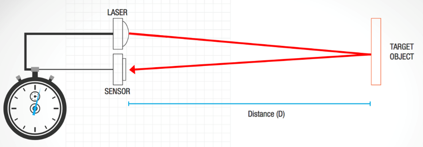
How does LiDAR build a 3D point cloud? LiDAR typically uses the direct time-of-flight (dToF) Automotive technique to measure the distance to an object. A short laser pulse is sent out and some of that light is reflected back by objects in the scene and detected by a sensor, such as the ArrayRDM-0112A20-QFN, to accurately record the time it took for the round trip of the laser pulse (see Fig. 1). Using the known speed of light, the distance can be calculated from this dToF measurement. This gives a single distance measurement within the field of view.
In order to build up a complete picture of the surroundings, this point measurement needs to be repeated at many different locations across the scene. This can be achieved by having fixed sensors and lasers that rotate and scan throughout the scene, or by using beam steering technology such as MEMS (micro-electro-mechanical systems) mirrors.
Figure 1. Illustration of dToF technique.
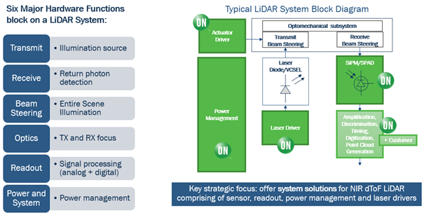
LiDAR systems, in general, rely upon the following key components: the illumination source, the sensor, optics, beam steering, signal processing and power management (Fig.2). For performance, the most critical elements are the illumination source and the sensor. The illumination is typically limited by eye safety considerations so that the greatest impact on system performance is often down to the sensor.
Figure 2. Anatomy of a dToF LiDAR System including the sensor element.
In many scenarios, the system will need to operate with the limited signal return, from distant or low-reflectivity objects where the signal may consist of only a small number of photons. Therefore, the sensor should be as sensitive as possible. The sensitivity of a LiDAR sensor is a combination of different factors. Firstly, the detection efficiency, which is the probability that an incident photon will produce a signal, is of prime importance. Then there is the sensitivity to low incidence flux or minimum detectable signal. Some sensors, such as PIN diodes have no internal gain and so a single detected photon will not register above the inherent sensor noise. An avalanche photodiode (APD) has some internal gain (~100x) but still, an incident signal composed of a small number of photons does not register above the noise, which requires it to integrate the returned signal for a certain duration of time. Sensors that operate in the Geiger mode, such as SiPMs (silicon photomultipliers) and SPADs (single-photon avalanche diodes), have internal gains of the order of a million (1,000,000x), and so even a single photon generates a signal that can be reliably detected above the internal sensor noise. This allows one to set a low threshold to detect the faintest of return signals.
While SiPMs and SPADs overcome many noise issues due to their high gain, in practical LiDAR applications there is another source of noise that needs to be considered – the ambient solar background or simply put sunlight. We are often seeking to detect very faint LiDAR return signals while being bombarded by unwanted light from the sun. So the problem becomes one of maximizing the signal (the returned laser light) while ignoring or minimizing the noise (sunlight). One way to do this is to take advantage of the single-photon sensitivity of the sensor and look for photons that are correlated in time.
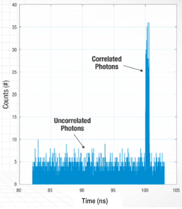
This method of multi-shot dToF measurement is achieved by repeating the procedure a number of times (multiple laser pulses resulting in a dToF measurement for each). Instead of calculating a distance for each measurement, each ToF value is added to a histogram or distribution plot. The result is a plot that looks like that shown in Fig. 3. The background counts are uncorrelated in time – that is, they arrive randomly in time relative to the time the pulse fired. These counts can be ignored since they are the noise due to sunlight. The peak represents counts that are correlated in time – a significant number of counts that all arrived with the same time value, indicating a signal from a target. This peak value can be translated to a distance for a particular frame and the process can start again. Even with several dozens of laser cycles per pixel per frame, frame rates of 30 fps can be achieved.
Figure 3. Example LiDAR ToF histogram
While a SiPM or SPAD sensor can use its single-photon sensitivity in conjunction with time-correlation techniques to see faint return signals, a PIN diode or APD sensor would simply miss these counts due to being lost in the solar background. Hence, these other sensor types simply cannot range as far or as efficiently.
How is depth information being employed in the real-world and how can LiDAR help? Consumer mobile applications have to date enabled many features via image sensor technology alone, for example using structured light. Time-of-flight (ToF) Automotive technology has been incorporated to some extent in mobile phones for a few years now to add depth sensing and enable photography features such as fast autofocus and “bokeh” portrait effects. Most recently, dToF imaging LiDAR sensors have been incorporated in the latest consumer mobile devices,, which provide better depth information over previous techniques and will no doubt greatly increase the number of mobile applications that make use of this data. The 3D information can be used to enable 3D mapping applications and improved augmented reality and virtual reality (AR/VR) experiences.
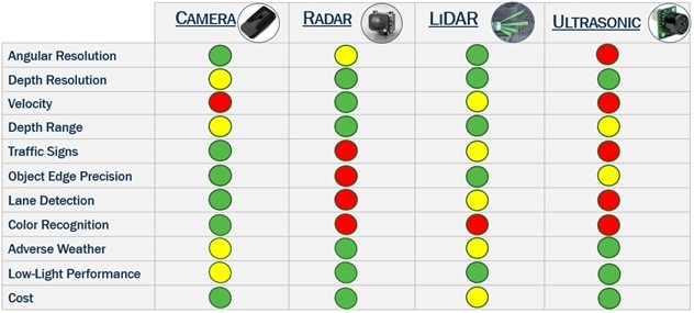
In automotive and industrial applications, where safety is key, the limitations of image sensors alone for object identification and hence autonomous decision-making and navigation, highlight the need for additional information via a fusion of different sensing modalities. LiDAR can be used in conjunction with other sensing technologies, such as cameras, ultrasonic and radar, to provide added redundancy, increasing the confidence level of the decision-making algorithms responsible for navigating or interacting with the environment. Each of these techniques has unique characteristics providing varying levels of information, with advantages and disadvantages in different situations.
Figure 4. Comparison of different sensor technologies
To enable high-performance LiDAR systems for automotive, a highly sensitive sensor, such as a SiPM, is the most efficient receiver. The SiPMs from ON Semiconductor offer an unparalleled combination of performance and operational parameters: high photon detection efficiency and low noise and dark count rates combined with low operational voltage, temperature sensitivity and process uniformity.
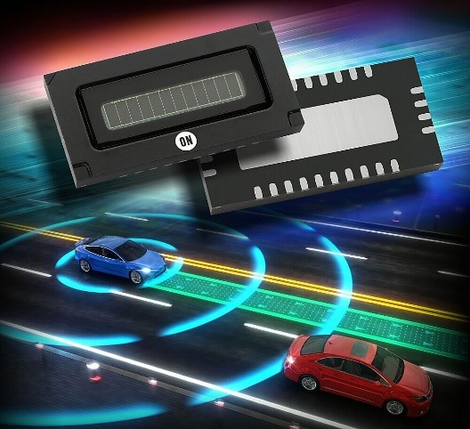
The ArrayRDM-0112A20-QFN, a 12-pixel linear array of SiPMs, addresses the market need for LiDAR. It features industry-leading 18% photon detection efficiency at 905 nm, the typical wavelength for a cost-effective, broad market LiDAR system. In addition, it is the first linear array of SiPMs commercially available and the very first automotive-qualified SiPM in the market.


