This blog is focused on the basic working of the variable speed drive – a critical component in enabling precise and accurate motor control in applications such as conveyors, winding, printing, extrusion machinery, and many other industrial applications. It is estimated that only between 20% and 30% of all deployed motors in the industry are inverter driven or connected to a variable speed drive. If each motor is driven in the most efficient way possible – that is with proper load matching and with an appropriate motor drive, it will have the potential to reduce global energy usage by up to 10%.
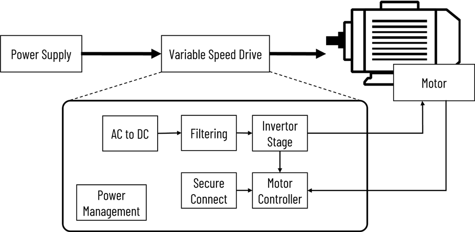
A variable speed drive (VSD) controls the speed and torque of an AC motor by converting fixed frequency and voltage input to a variable frequency and voltage output to achieve precise control of motor speed and torque. It helps in optimizing energy consumption, increasing productivity, extending equipment lifetime, and enhancing the overall efficiency of motor-driven systems. Motor drives are primarily located between the AC grid and the motor. They take their main power source from the AC grid and convert the AC supply voltage to DC using a rectifier and a capacitive filter. The filter capacitor bank helps to reduce the AC ripple on the DC bus. After smoothing, the DC voltage is applied to the inverter stage.

The inverter stage is the most important in the variable speed drive as it converts the DC input into a variable-frequency output. It consists of power transistors, isolated gate drivers, voltage and current feedback circuits, as well as other protection and monitoring circuits. The power transistors convert the high voltage DC bus to variable frequency, variable voltage three-phase AC output for the motor. In the inverter stage, gate drivers turn on and off the power transistors using PWM signals from the motor controller to vary the AC output (voltage and frequency) required by the motor, depending on its load. The gate drivers efficiently turn on and off the power transistors and regulate the output voltage and frequency while also protecting them from any fault conditions. The voltage and current sense circuitry play a crucial role in measuring the current and voltage in the motor and feeding these values back to the current control loop. The motor current is a direct function of the motor torque and the bandwidth of the current control loop determines the overall torque response of the variable speed system. Precise and robust measurement is important to ensure maximum torque per ampere of current and optimize motor efficiency. This in turn saves energy and enhances sustainability.
The inverter is directly connected to the motor itself. In many systems, the motor will have an encoder device attached to it, that measures the position of the motor rotor and feeds this back to the motor controller. The motor controller is the processing unit that takes input from the encoder, the inverter, and any external connectivity interfaces, and transmits output optimized pulse width modulation signals back to the inverter to run the motor efficiently. The choice of the processor depends on the application and compute power requirement, it can be a microcontroller, an FPGA, a high performance microprocessor, or a combination of these. The secure connect block is where the user and network interface interact with the motor drive. Connectivity and security are becoming critical elements of the motor drive to enable communication with the outside world. Since motor drives operate in harsh noisy environments for reliable operation, it is essential to design connectivity solutions with added noise immunity and robustness. With increased connectivity comes the need for added security at the device level. Manufacturers have to protect production assets from malware attacks, and untrusted commands to ensure secure boot and trusted execution, ensuring secure communication across the network.


