Simulation is a convenient medium for running experiments, as you can run a lot of tests relatively quickly and cost effectively, fewer wind tunnels required. To show that you can trust the results when modeling transonic flow, we have created a validation model based on the famous ONERA-M6 wing.
Modeling Flow at Transonic Speeds with COMSOL Multiphysics
When you add the CFD Module to the COMSOL Multiphysics® simulation platform, you gain access to functionality that is specialized for modeling fluid flow, including various predefined physics interfaces. Broadly speaking, physics interfaces define a system of equations, analyses, meshes, studies, and solvers, as well as the results evaluation and visualization features applicable to a certain engineering field or physics phenomenon. You always have access to the fundamental physics interfaces included in the COMSOL Multiphysics platform, but you can extend the list of available interfaces by adding the modules that are relevant to your work, such as the CFD Module in this case.
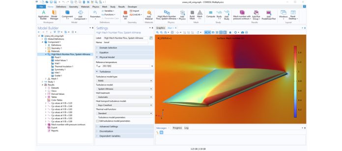
The COMSOL Multiphysics user interface with the High Mach Number Flow interface from the CFD Module in use. The Graphics window shows the results after solving the ONERA-M6 wing model.
To model transonic flow over wings with COMSOL Multiphysics, you would add the CFD Module and use the High Mach Number Flow interface, preferably with the Spalart–Allmaras turbulence model, which is a one-equation model that was developed for aerodynamics.
About the ONERA-M6 Wing Model
The ONERA-M6 wing was originally created in the 1970s for validating (3D) computer models involving flow at transonic speeds and high Reynolds numbers. By comparing our results to the data that came out of the ONERA-M6 experiment, we can verify that the COMSOL model is accurate. Our validation model is based on CAD geometry of the wing provided by the Langley Research Center at NASA, which we imported into COMSOL Multiphysics using the CAD Import Module.
Results and Validation
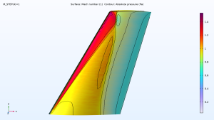
After running and solving the model, we can visualize the Mach number and pressure on the wing using surface and contour plots. The results show two weak shocks along the wing’s surface:
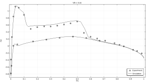
How does this compare to the ONERA-M6 wing experiment? By plotting our simulation results and the results from the wind tunnel experiment, we see that there is good agreement between the two. In short, the model accurately depicts both the location of the shocks and the magnitude of the jumps in the pressure coefficient. You can flip through the results comparisons here:
Try It Yourself
Ready to take the model for a test flight? All of the model files, including step-by-step instructions, are available for download from the Application Gallery as of COMSOL Multiphysics version 6.1.
The ONERA-M6 model is just one of many verification and validation models available for download. Learn more and access the complete collection via the blog post titled “Now Available: Collection of COMSOL Verification and Validation Models”.
This model uses data from the ONERA-M6 wing as a reference. This model is not affiliated with, endorsed by, or sponsored by ONERA.
Transonic Flow over the ONERA M6 Wing
This example demonstrates how to set up the classical external-flow problem of solving for the high-speed, compressible, turbulent flow over the ONERA-M6 wing. The problem involves finding a steady-state solution of the flow field around the 3D, swept wing geometry, immersed in a transonic flow at a moderately high angle of attack. The solution indicates the formation of weak shocks on the upper surface of the wing.
Disclaimer: This model uses data from the ONERA-M6 wing as a reference. This model is not affiliated with, endorsed by, or sponsored by ONERA.


