Residual-current devices, commonly referred to as RCDs, are used in many practical applications. They can be found in fuse boxes, electrical switchgears or industrial machine control systems. A residual-current device (RCD), protects the user of the installation against electric shock. Therefore, not only the efficiency and reliability, but also the proper connection of this device is important.
Residual-Current device – construction and types
To properly understand the operation and connection of residual-current devices, it is worth to consider the design of RCDs. It is best to focus on the four basic elements of residual-current devices.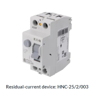
- Contacts with switching lever;
- Summation current transformer, the so-called Ferranti relay – ferromagnetic enclosure through which the phase and neutral conductor pass;
- Tripping mechanism – usually a polarized trip relay;
- Residual-current device test circuit – allows you to check the correct operation.
Connect the phase and neutral wires to the contacts; the switch lever will allow you to switch on the residual-current device. The connected device is marked in red; when the contacts are connected to each other, the current can flow through them. If the lever is lowered, the contacts are open; this is indicated in green. A switched-off residual-current device is shown in the graphic above.
The current transformer is the key component of the RCD, thanks to which the device works. It measures the difference between current flowing through the conductors. This value should be 0A.
Another element related to the current transformer is the trip relay. If the measurement made by the transformer shows an imbalance (difference) in the current in the conductors, the RCD will trip, cutting off the electricity supply.
The operation of the RCD should be checked at least once a month. After pressing the button on the switch, the test circuit will be started, which will simulate a difference between the currents in the live and neutral wires of the appliance then the device should work and cut off the electricity supply.
Types of residual-current devices
- Type A RCDs– trip on sinusoidal residual current.
- Type B RCDs– advanced devices, trip on sinusoidal residual current, pulsating or continuous direct current up to 1000Hz.
- AC type residual-current devices– trip on sinusoidal residual current and on pulsating rectified current.
In addition, RCDs are divided into three groups according to their sensitivity:
- High-sensitivity, tripping on 10mA or 30mA residual current. They are most often used in homes and apartments.
- Medium sensitivity, disconnecting the power supply when 100mA, 300mA, or 500mA differential current is detected.
- Low sensitivity, disconnecting the power supply when the residual current value exceeds 500mA. They are most often used in industrial enterprises.
How Residual-Current device (RCD) works?
The operation of the residual-current device has already been briefly discussed, but it is worth taking a closer look. Residual-current device uses the phenomenon of electromagnetic induction to operate. As already mentioned, in theory, the difference between the incoming and outgoing current should be zero. In practice, however, it is usually a maximum of 30mA. The residual-current device disconnects the circuit if the residual current exceeds a certain value. Such malfunctions may not be detected by the standard protections such as overcurrent circuit breakers.
It is important to know that residual-current devices are much more complex than conventional fuses or circuit breakers. As a result, they are much more sensitive to all kinds of disturbances in the electrical circuit. This is a common reason for the malfunctioning of residual-current devices.
We should also remember that the residual-current device cannot protect us from direct contact with the electric wire. Disconnect the power supply before any activities!
How to connect the RCD – Installation Diagram
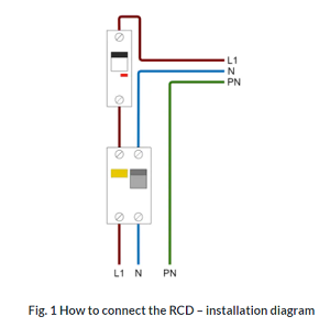
The connection of a residual-current device is relatively simple, but a few rules must be followed. An RCD must not be used as a single element between the power source and the load. It does not protect against short circuit or overheating of the wires. For more safety, a combination of RCD and overcurrent circuit breaker, at least one for each RCD, is recommended.
Connect the phase (brown) and neutral (blue) wires to the RCD input in a single-phase circuit. The protective conductor is connected with e.g. a terminal strip.
The phase wire at the RCD output should be connected to the overcurrent circuit breaker, while the neutral wire can be connected directly to the installation.
Connection of a three-phase RCD
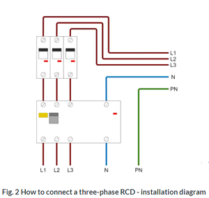
In more complex electrical systems, in more complex electrical systems, the connection of the RCD is similar to the connection in a single-phase circuit.
Connect all three phases and the neutral wire to the input of the residual-current device. An overcurrent circuit breaker is connected at the output to each phase. On the other hand, the neutral wire at the output is connected to the busbar.
For this connection, pay attention to the maximum current that can flow through the RCD (rated current of the RCD).
Why does the RCD trip?
RCD tripping is often discussed on Internet forums. There are many reasons for this: if there was no problem with the RCD for a long time, and it suddenly started tripping, the problem may be a faulty installation or a faulty appliance. If the installed switch causes problems from the very beginning, the fault may be its incorrect connection or wrong selection for our installation. When choosing the right residual-current device for your household, pay attention to the following parameters:
- Rated voltage – it should not be lower than the mains voltage;
- Residual current – limits the amount of current that can flow through the RCD. The RCD triggers when the tripping current is reached;
- Rated current – this parameter allows us to know the maximum current that can flow through the contacts.


