A coulomb counter can measure charge that flows into or out of a battery, and small, dedicated ICs can directly interface with low-to-medium battery voltages of up to about 20 V. By using a high-voltage amplifier as a level shifter, you can extend the input operating range to much higher voltages of the measurement circuit. The LT6375 voltage-difference amplifier includes some features that make this circuit work accurately up to surprisingly wide voltages.
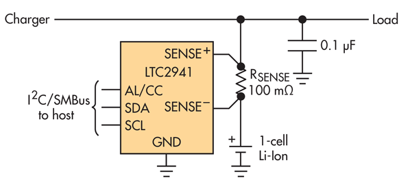
Coulomb counters operate by measuring the voltage across a sense resistor as an indication of the current that needs to be integrated. Fig. 1 shows the typical connection when using the LTC2941, a low-voltage coulomb counter. The important point is that a coulomb counter really measures voltage, then interprets it as current, and later reports it as charge. By removing the sense resistor, and somehow driving another voltage across the coulomb counter’s sense pins, it will still interpret that voltage as a current and report an accumulated charge.

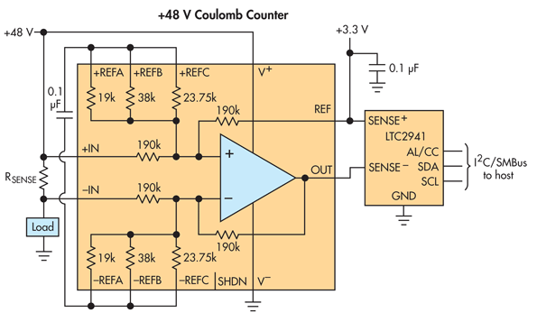
In Fig. 2, the LT6375’s output is connected to the sense pins of the coulomb counter. The IC is a difference amp, which means it’s an op amp plus precision resistors connected so as to shift the level of a differential input voltage. The operation of the difference amp drives its output voltage to a value of:
OUT = REF + GAIN × [(+IN) – (-IN)]
The LT6375 drives its output pin, but the REF pin must be connected to a low-impedance source. Similarly, the LTC2941 expects a low-impedance source at its SENSE+ pin, which is also the supply pin for that IC. You can connect both REF and SENSE+ to the same logic rail used for the I2C interface (such as 3.3 V). By connecting the LT6375’s OUT pin to the SENSE– pin, the LT6375 will impose the difference between its inputs across the inputs of the LTC2941. In effect, the LT6375 acts as a fake sense resistor.

The accuracy of a difference amp depends to a great extent on the resistor matching. While it’s obvious that resistor mismatch directly affects gain accuracy, it’s less obvious and a more serious concern that this resistor mismatch will cause offset errors. A 1% resistor mismatch would cause an output offset equal to 1% of the voltage over which the circuit level shifts.
For example, a 48-V input that’s level-shifted to 3 V would result in 450 mV of offset error, which is much too large for this kind of measurement. The LT6375A specifies a minimum common-mode rejection ratio (CMRR) of 97 dB, which means that a 45-V level shift causes an offset of less than 640 μV.
When designing a high-voltage level-shift circuit, it’s critical to ensure that the op amp’s inputs stay within their valid operating range. For the LT6375, the supply pin is rated up to 60 V, so in some cases, it can be powered from the voltage being measured. This is the arrangement of Fig. 2, where the LT6375 measures current from a 48-V supply.

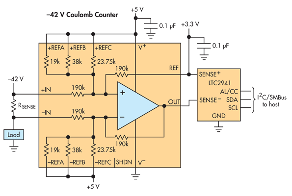
Finally, the IC includes additional precision resistors that can be configured by external pins to divide the input common-mode range, while keeping the differential gain equal to unity. In Fig. 3, the auxiliary reference pins are all connected to the 5-V supply, which divides the –42-V input voltage to bring it within the op amp’s supply range. For other applications, the op amp within the LT6375 has a unique feature whereby its inputs can operate at voltages higher than the supply pin itself. Combining these features, you can design circuits that can monitor supplies across an input range of ±270 V.
Kris Lokere is the strategic applications manager for signal-conditioning and mixed-signal products at Linear Technology Corp. He and his team are responsible for amplifiers and high-performance ADCs. Kris has designed multiple op amps and received his MSEE degree from the Katholieke Universiteit Leuven, Belgium.


