

Courtesy : Microchip
As EEPROM devices shrink, board space can be freed for exciting uses. However, smaller EEPROM means smaller cell sizes. This in turn means thinner cell oxide layers. These can wear out more easily, raising reliability concerns. Many manufacturers defend against cell wear out with Error Correcting Codes which detect and correct errors. This solution is usually hidden, with no way of knowing whether it’s there or if it was invoked. Thus, ECC should be seen as a safety feature, not a sole reliability solution. That’s why Microchip Technology, with over 30 years of EEPROM experience, has developed a new family of EEPROM with Error Correction Status. ECS alerts users when error correction occurs, indicating that a memory block should be retired. This feature takes error correction one step further, acting as a powerful reliability multiplier for stand-alone EEPROM, and providing transparency and control designers can enjoy.
Error Correction
As mentioned, most new EEPROMs include Error Correcting Codes, typically designed to correct single-bit errors for each specified number of bytes. There are multiple types of ECC used, the most common being Hamming codes. ECC adds parity bits calculated from stored data. When data is read back, the parity bits are recalculated from stored data and compared to the parity bits stored in memory. Discrepancies indicate errors, and the pattern of the discrepancy allows the system to pinpoint and correct single-bit errors, restoring the data and allowing the memory block to continue to be used. However, many EEPROMs don’t indicate when corrections occur, leaving you unaware of deteriorating blocks. ECC then can only be used as a safety feature, giving the application a marginal endurance extension so it may last a bit longer without corrupted data. If you need to know if a block is truly worn out, you can add manual checks to verify memory after each write, but this is resource intensive. Error Correction Status on the other hand solves this challenge because it automatically flags you when a block becomes worn-out, enhancing reliability without needing to invest a large amount of resources.


System Considerations
The advantage of ECS shines the most within wear-leveling routines. How does wear-leveling work? Let’s begin with system design considerations and explain how wear leveling works, then we will show how to use ECS to enhance a wear-leveling routine.
Regardless of whether your EEPROM has ECC or not, it’s crucial to consider its endurance, typically rated at 100,000 cycles for MCU-embedded EEPROM and 1 million cycles for standalone EEPROM at room temperature. Designers must account for this by estimating the number of write cycles over the typical lifetime of the application to determine what size of an EEPROM they need and how to allocate data within the memory.
For instance, consider an industrial power distribution system in a building with four sensors, one for each machine that workers can use when needed. Each sensor generates a data packet per usage session, recording things like energy consumption, session duration and timestamps. Data is stored in the EEPROM until a central server requests a data pull. The system is designed to pull data frequently enough to avoid overwriting existing data within each packet. Assuming a 12-year application lifespan and an average of 400 daily packets per sensor, the total cycles per sensor will reach 1.752 million, greatly surpassing the typical EEPROM endurance rating. To address this, you can create a software routine to spread wear out across the additional blocks (assuming you have excess space). This is called wear-leveling.
Wear-Leveling: Dynamic and Static
To implement wear-leveling, you can purchase an EEPROM twice as large, allowing you to allocate 2 blocks per sensor, providing up to 2 million cycles per sensor. This offers a buffer of additional cycles if needed (an extra 248 thousand cycles per sensor).
You will then need some way to know where to write new data to spread the wear. While you could write each block to its 1-million-cycle-limit before proceeding to the next, this approach may lead to premature wear if some sensors generate more data than others. If you spread the wear evenly across the EEPROM, the overall application will last longer. Figure 1 illustrates the example explained above, with four meters sending data packets (in purple) back to the MCU across the communication bus. The data is stored in blocks within the EEPROM. Each block has a counter in the top left indicating the number of erase-write cycles it has experienced.
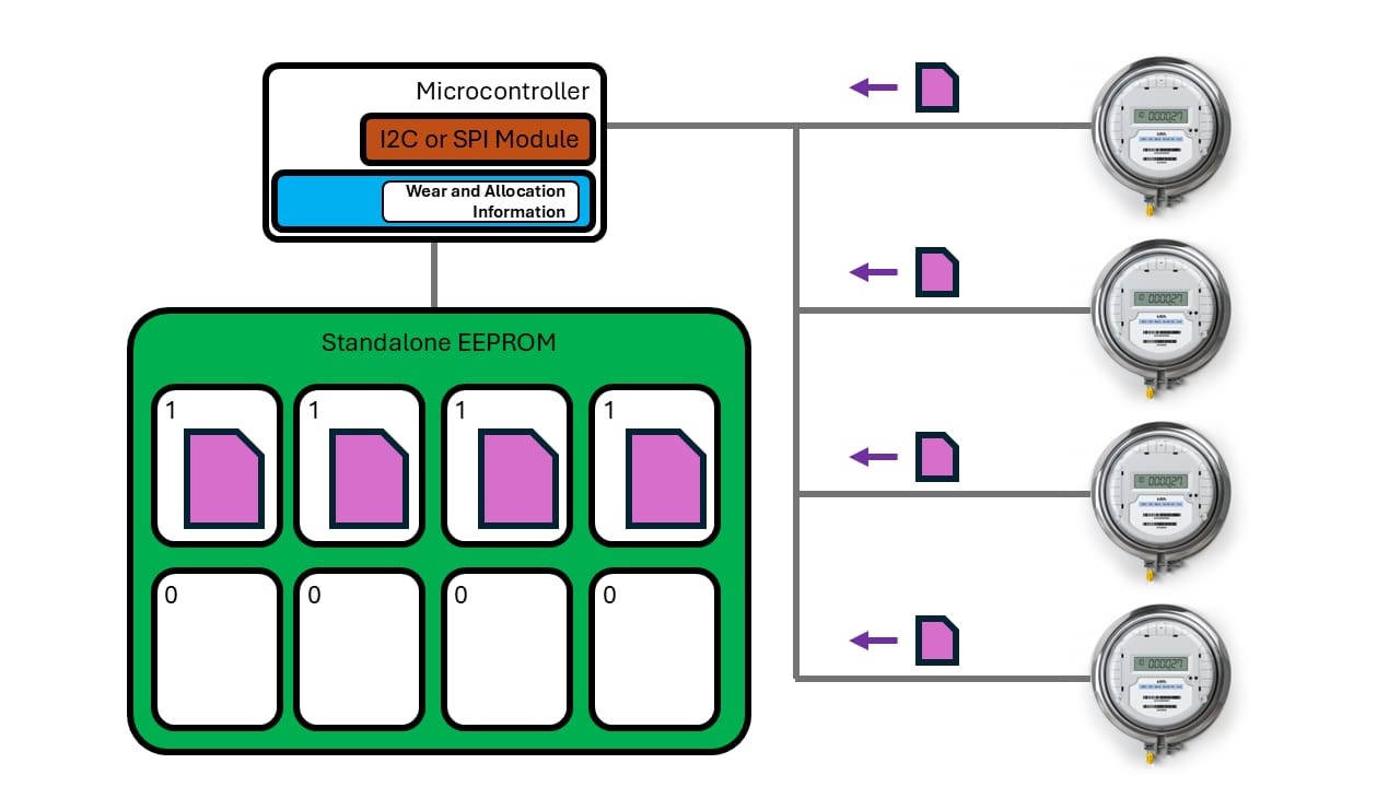 |
Figure 1
There are two types of wear-leveling: dynamic and static. Dynamic wear-leveling is simpler, spreading wear over frequently changing memory blocks but can result in uneven wear. Uneven wear caused by this type of wear-leveling is illustrated in Figure 2. The other type: static wear-leveling, spreads wear across the entire EEPROM, extending the life of the entire memory. Static wear-leveling requires more CPU overhead; however, it will produce the highest endurance for the life of the application.
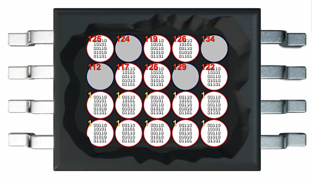 |
Figure 2
Wear-leveling involves monitoring each memory block’s write cycles and allocation status, which itself can cause wear in non-volatile memory. To deal with this, one option is to store this information in your MCU’s RAM, which doesn’t wear out. Since RAM loses data on power loss, you may consider designing a circuit to detect power loss early, allowing time to transfer current register states to NVM.
Implement Wear-Leveling in Software
In general, a software approach to wear-leveling is to create an algorithm which directs writes to the block with the fewest previous number of writes to spread wear. In static wear-leveling specifically, data is stored in the least-used location not currently allocated for anything else, and data will be swapped to new locations if the cycle difference between blocks is too large. Each block’s write cycles are tracked with a counter, and blocks are retired when they reach their maximum endurance rating.
Wear-leveling effectively reduces wear and improves reliability, allowing each block to reach its maximum specified endurance (Figure 3). However, endurance specifications are only rough indicators of the physical life of the block and don’t include early failures. Also, many blocks will last much longer in the real-world than their endurance ratings allow for. To ensure even higher reliability, additional checks are needed. One method is to read back and compare the block just written to the original data, which requires bus time, CPU overhead and additional RAM. This readback should occur for every write, especially as the number of writes approaches the endurance limit, to detect cell wear-out failures. Without readbacks, wear-out and data corruption may go undetected. The following software flowchart illustrates an example of static wear-leveling, including the readback and comparison necessary to ensure high-reliability. This implementation has the disadvantage of spending significant system resources on reliability.
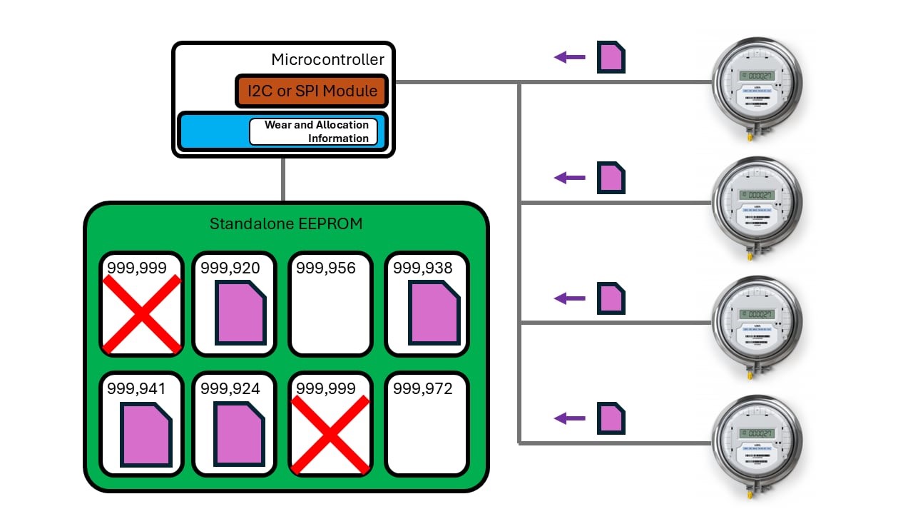 |
Figure 3
Using Error Correction Status with Wear-Leveling
Error Correction Status enables a new data-driven approach to wear-leveling and significantly enhanced reliability without the need for full data readbacks.
ECS indicates when a single-bit error has been detected and corrected. This allows you to check a status register to see if ECC was invoked, reducing the need for full memory block readbacks (Figure 4). When an error is detected, the block can be retired, providing data-based feedback on memory wear-out instead of relying on a blind counter. This eliminates the need to carefully estimate memory lifespan and is beneficial for systems that experience vast shifts in their environments over their life, like dramatic temperature and voltage variations which are common in the manufacturing, automotive and utilities industries. This approach allows you to extend memory cell life beyond the datasheet endurance specification all the way to true failure, potentially allowing you to use the device much longer than before.
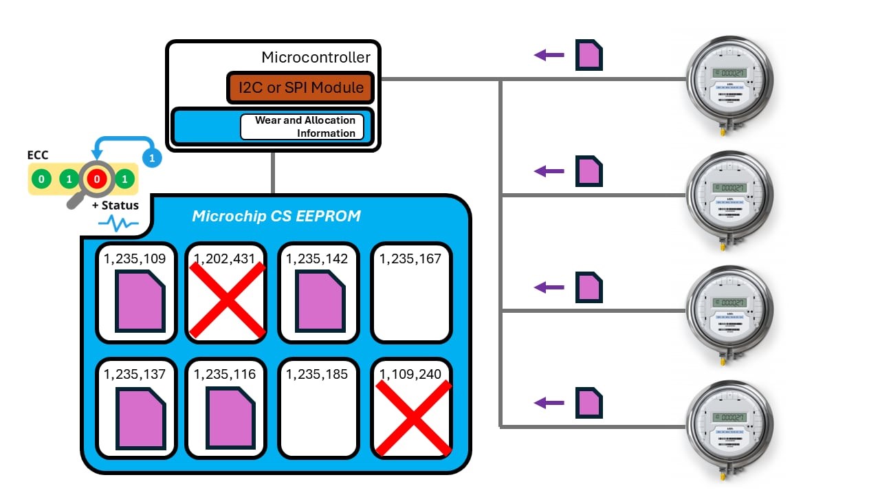 |
Figure 4
This data-driven approach to wear-leveling is more reliable than classic wear-leveling because it uses actual data instead of arbitrary counts—if one block lasts longer than another, you can continue using that block until cell wear out. It also reduces bus time, CPU overhead and required RAM, which in turn lowers power consumption and improves system performance. Your software flow can now be updated to accommodate this new status indicator (Figure 5).
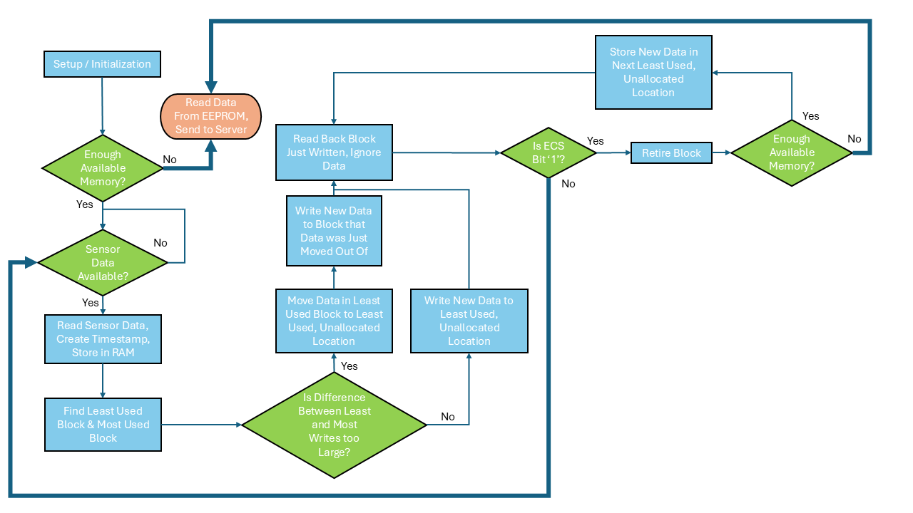 |
Figure 5
As illustrated in the flowchart, using an ECS bit simplifies the software flow by eliminating the need to read back data, store it in RAM and perform comparisons, freeing resources to create conceptually simpler software. Although a data readback is still required to evaluate the status bit, the data can be ignored, reducing RAM and CPU overhead. The frequency of status bit checks depends on block size and the smallest file size the software handles.
The following devices offer ECS and are currently released and available for order:
- I2C EEPROMs: 24CSM01 (1 Mbit), 24CS512 (512 Kbit), 24CS256 (256 Kbit)
- SPI EEPROMs: 25CSM04 (4 Mbit), 25CS640 (64 Kbit), 25CS320 (32Kbit)
The overall benefit of ECS is significant and will allow you to see cell health in a way you could not before. Some of the advantages are:
- Maximize EEPROM block lifespan by running cells to failure
- Option to remove full block reads to check for data corruption, freeing up time on the communication bus
- If wear-leveling is not necessary or too burdensome to the application, the ECS bit serves as a quick check of memory health, facilitating the extension of EEPROM block lifespan and helping to avoid tracking write cycles
Reliability Improvements with ECS
Implementing error correction with a status indicator revolutionizes reliability and extends device life, especially within wear-leveling schemes. This advancement is a game-changer for automotive, medical and other safety-critical applications, offering unparalleled reliability. Designers striving for excellence will find this approach indispensable in creating top-tier systems that stand the test of time. Remember, using our new CS EEPROM will allow you to take hold of your reliability destiny. For more information, be sure to check out our CS family of EEPROM products.