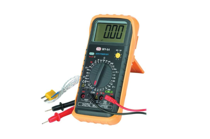
A digital multimeter (DMM) is an electronic measuring instrument that combines multiple functions into one device. It can measure voltage, current, resistance, and often additional parameters like capacitance, frequency, temperature, and continuity. The readings are displayed on a digital screen, providing high accuracy and ease of use.
History of Digital Multimeter
- Analog Origins: Multimeters began as analog devices, using moving needle mechanisms to display measurements.
- First Digital Multimeter: In the 1970s, advancements in digital electronics led to the development of the first digital multimeters. Early models were bulky and expensive but offered better accuracy than analog counterparts.
- Modern Developments: Over the decades, DMMs have become compact, affordable, and feature-rich, with advanced functionalities such as wireless connectivity and data logging. Companies like Fluke, Tektronix, and Keysight have pioneered innovation in this field.
Types of Digital Multimeters
- Handheld Multimeters:
- Portable and commonly used for general-purpose applications.
- Bench Multimeters:
- Larger and more precise; used in laboratories and industrial settings.
- Clamp Multimeters:
- Specialized for measuring current without direct contact with the conductor.
- Autoranging Multimeters:
- Automatically select the appropriate measurement range for the parameter being tested.
- Fluke Digital Multimeters:
- Known for ruggedness and reliability, often used in industrial applications.
Block Diagram of a Digital Multimeter
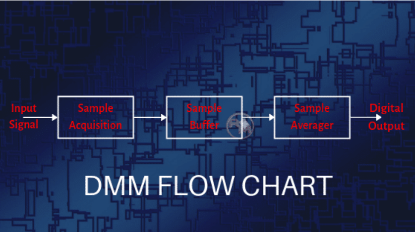
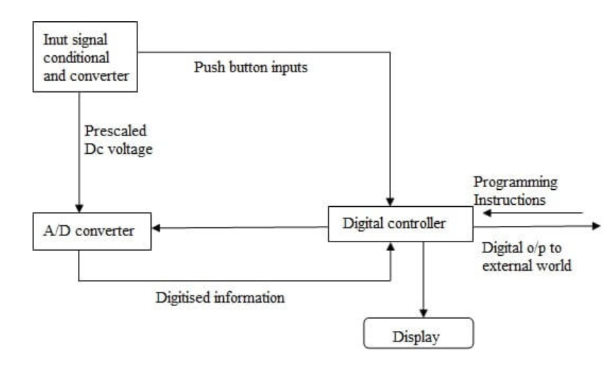
The operation of a Digital Multimeter (DMM) is based on precise voltage measurement, which serves as the foundation for calculating other parameters like current and resistance using mathematical relationships. Below is an explanation of the working process alongside a conceptual block diagram.
Working Principle
The key process in a digital multimeter involves the measurement and conversion of an analog input voltage into a digital output, which is displayed numerically. The conversion is achieved using a Successive Approximation Register (SAR) Analog-to-Digital Converter (ADC), which is widely employed in DMMs for its speed and accuracy.
- Sample and Hold:
- The first stage of the DMM involves sampling the input voltage.
- The sampled voltage is held steady to ensure accurate processing.
- Operational Amplifier (Op-Amp):
- The sampled input voltage is fed into an operational amplifier.
- The second input of the op-amp receives feedback from a Digital-to-Analog Converter (DAC) that operates in tandem with the SAR ADC.
- Successive Approximation Register (SAR) ADC:
- The SAR ADC determines the digital equivalent of the analog input voltage with high resolution.
- The process begins by setting the Most Significant Bit (MSB) to “1” and others to “0” (e.g., 1000 for a 4-bit system).
- Based on comparisons of the input voltage with the DAC output, subsequent bits are adjusted iteratively.
- Digital Output:
- The SAR ADC provides a stable digital output corresponding to the analog input.
- This result is processed and displayed on the DMM’s digital screen.
Block Diagram
Here’s a high-level description of the components in a DMM:
- Input Section:
- Probes connected to the circuit under test.
- Selector Switch to choose the measurement type (voltage, current, resistance).
- Sample and Hold Circuit:
- Captures and holds the input voltage for processing.
- Operational Amplifier (Op-Amp):
- Amplifies the sampled signal and compares it to feedback from the DAC.
- Digital-to-Analog Converter (DAC):
- Converts the digital output of the SAR ADC back to an analog signal for comparison.
- Successive Approximation Register (SAR) ADC:
- Converts the analog signal into a digital value with high resolution.
- Microcontroller/Processor:
- Processes the digital signal and controls the display output.
- Display Unit:
- Displays the measured value numerically.
Operation Example (4-bit SAR)
For a 4-bit SAR ADC:
- Initially, the output is set to 1000 (MSB = 1).
- If the input voltage is less than half the full-scale range, the comparator output is low, forcing the register to 0100.
- If the voltage exceeds this value, the output progresses to 0110, and so on.
- The process continues until the digital output closely matches the analog input.
This iterative approach ensures precise measurement of the input voltage.
How to Use a Digital Multimeter
- Safety First: Ensure the multimeter is in good condition and the probes are not damaged.
- Set the Mode: Use the rotary dial to select the parameter you want to measure (voltage, current, resistance, etc.).
- Connect the Probes:
- Insert the black probe into the COM port.
- Insert the red probe into the appropriate port based on the measurement.
- Take the Measurement:
- For voltage, connect the probes across the two points.
- For current, break the circuit and connect the probes in series.
- For resistance, connect the probes across the resistor.
- Read the Display: The measurement appears on the screen.
Digital Multimeter Uses
- Testing and troubleshooting electrical circuits.
- Measuring battery voltage and capacity.
- Diagnosing automotive electrical issues.
- Checking continuity in wiring and connections.
- Monitoring industrial equipment and machinery.
- Research and educational experiments.
Advantages of a Digital Multimeter
- High Accuracy: Provides precise measurements with minimal error.
- Ease of Use: Digital readouts are easy to interpret, reducing the chance of misreading.
- Versatility: Combines multiple measurement functions in one device.
- Portability: Compact and lightweight, ideal for fieldwork.
- Safety Features: Built-in protections for high-voltage measurements.
- Advanced Features: Options like autoranging, data logging, and connectivity enhance functionality.
A digital multimeter is an indispensable tool for anyone working in electronics, electrical engineering, or related fields.


