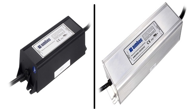
Aimtec’s AC/DC LED driver series AMEPR30-AZ, AMEPR60-AZ, AMER90-AZ, AMER120-AZ, and AMER150-AZ all can be utilized in either a Constant Current or a Constant Voltage mode.
Constant Current Mode
The drivers are equipped with a current limiting circuit set to the maximum rated current for the specific driver model. As a result, when a load is installed at the output of the driver that would normally result in a high current above the maximum, the current limit circuit forces the driver to operate in constant current mode. When a LED load is installed the driver will operate in Constant Current mode. The output voltage will be the total forward voltage of the LED load.
Constant Voltage Mode
With a load resistance (it would be better to use this term because the load can be complex and pulsing) that results in current below the driver’s maximum it will operate in Constant Voltage mode with the load voltage being the maximum rated voltage for the driver model. The load current will depend on the load resistance and will follow Ohm’s law,
Iload = Vmax/Rload.
Practical use
Using Aimtec’s 60W AMEPR60-24250AZ as an example: it has a maximum rated current of 2.5A with a voltage range from 12 to 24VDC.
- Constant Voltage Area (A),
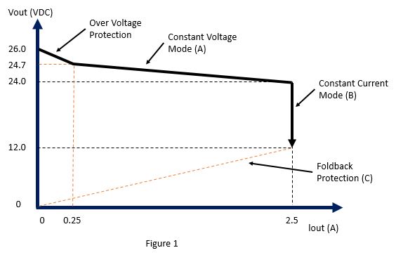
The constant voltage area (horizontal line on on Fig. 1 [below]) begins from zero loading (no load current). Overvoltage protection (OVP) engages at this point and the output voltage is limited to 26.0VDC. When there is a small load current, for example 50mA, the output voltage decreases to 24.7VDC. With increased loading (decreased load resistance) the output voltage will decrease gradually. When the output current reaches the driver’s maximum of 2.5A, the output voltage will be 24VDC (Rload=24V/2.5A=9.6 Ohm). This is the point where the driver switches mode into constant current mode (B). With loading from no loading to 9.6 Ohm the driver operates as a conventional AC/DC converter.
- Constant Current Area (B)
The constant current area (vertical line on Fig. 1 [below]) is the area where the output current is stable (fixed), however, the output voltage will decrease with increased loading (decreasing load resistance). For example, with Rload=9 Ohm, the output voltage will be 2.5A x 9 Ohm=22.5VDC, with Rload=6 Ohm, the output voltage will be 2.5A x 6 Ohm=15VDC.
The output voltage will continue to decrease with increased loading (decreased load resistance) until it reaches 12VDC (Rload=12V/2.5A=4.8 Ohm). This is the switching point for the operating mode to foldback protection.
- Foldback Operation (C)
Foldback protection mode (dotted sloping line). If the output current increases above the driver’s maximum rated current of 2.5A the driver’s Over Current Protection (OCP) will engage and the voltage and current will decrease rapidly. The driver will switch into this mode when the load resistance is less than 4.8 Ohm. As the current increases, the voltage will decrease to limit the output power of the driver to a safe value.

More information on Aimtec’s AC/DC LED driver series AMEPR30-AZ, AMEPR60-AZ, AMER90-AZ, AMER120-AZ, and AMER150-AZ can be found on Transfer Multisort Elektronik website, tme.eu. TME is an authorized distributor of Aimtec.


