Basics of Operational Amplifiers and Comparators
A quick look at the portfolio of any major Integrated Circuit (IC) supplier will reveal a plethora of various amplifier ICs. This includes the well-known operational amplifier (op amp) and other more specialized amplifiers such as instrumentation, current sense, difference, and transimpedance amplifiers, just to name a few. Even the seemingly basic comparator IC often gets lumped into the category of amplifiers.
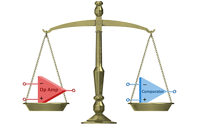
While there is a lot of functional overlap among these various amplifier types, each is designed to excel at various functions or use cases. This post will take a closer look at two common ICs—operational amplifiers and comparators—and explore the possible pitfalls of using an op amp as a comparator.
Overview of Op Amps and Comparators
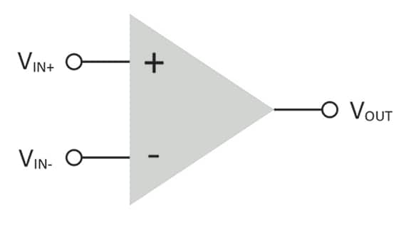
Let’s begin with a very high-level look at these two types of ICs. At first glance, they are quite similar; even the electrical circuit symbol for op amps and comparators is the same—a triangle with a positive and negative input and a single output. But the actual design and intended use of these two types of ICs are quite different.

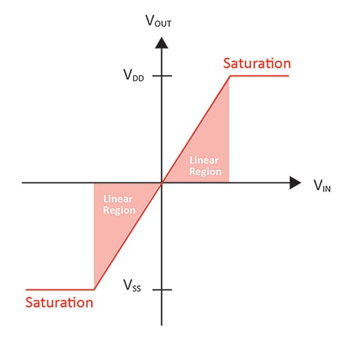
An operational amplifier is designed to work with negative feedback, which means the output of the amplifier is connected to the inverting (negative) input. The way in which this negative feedback loop is constructed will determine the operation (hence the name) of the amplifier. Examples include creating a low-pass or high-pass filter, amplification, integrator, voltage follower, and more. As a result of this negative feedback, an op amp’s output stage is designed to work in the linear region, simply meaning between the supply rails of the amplifier.
Comparators, on the other hand, have an output stage that is specifically designed to work in saturation, meaning the output voltage is always close to one supply rail or the other, not in between. The lack of negative feedback in a comparator and the design of the output stage are the big differences between op amps and comparators.

Using an Op Amp as a Comparator
In general, if a given design calls for a comparator, it is best to simply use a comparator. Such a device is designed and optimized specifically for that function and hence will provide the best results. But a situation may arise in which using an op amp for a comparator function is attractive. For example, if a given design contains an unused op amp and a comparator is needed, then utilizing that op amp as a comparator will save time, board area and cost. With this in mind, let’s explore some of the possible pitfalls in utilizing an op amp as a comparator.
Let’s begin by considering the input stage of the op amp. Not all op amps provide for a rail-to-rail input stage, so care must be taken to ensure that within the given application, the input common mode range of the op amp is not exceeded. Another possible concern pertaining to the input stage is the differential input range of the op amp. Some op amps have back-to-back diodes that prevent the inverting and non-inverting inputs from moving more than a diode drop apart. This is more common within bipolar op amps and some higher voltage op amps. The absolute maximum ratings within the op amp data sheet should indicate any limitation in the differential input range.
There are also several considerations regarding the output stage of the op amp when evaluating whether it will function correctly as a comparator within your application. When utilized as a comparator, the speed of the output transitions from one rail to the other will be determined by the slew rate of the amplifier. Care must be taken to ensure that the speed of the resulting comparator is fast enough for the given application. It should also be noted that in certain situations, this can be considered an advantage; the slew rate will limit the edge rate, reducing electromagnetic interference-related issues. As noted previously, op amps are designed to work within the linear region of operation, meaning between the supply rails. When the output of the amplifier is forced to the supply rails, the amplifier output recovery time may be long, if it is specified at all. Finally, an operational amplifier’s output stage is designed to always source or sink current, hence there is no way to create a comparator function with an open-drain output. Given that comparators essentially have an analog input and a digital output (one of two states determined by the inputs), comparators are often used to bridge different circuit characteristics—converting signals to a different voltage range for example. Consequently, utilizing a comparator with an open-drain output is quite common.
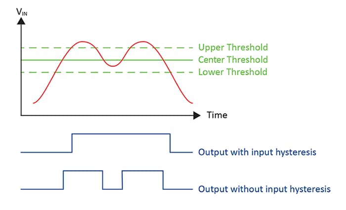
An additional consideration when evaluating whether to use an op amp as a comparator is hysteresis. A comparator with hysteresis utilizes an “upper” and “lower” threshold, in which the input signal must pass above or below these respective thresholds before the output will transition. This is useful for input signals that are electrically noisy or slow moving. Most comparator ICs offer built-in hysteresis, with some even offering adjustable hysteresis. Configuring an op amp as a comparator operating in open loop (meaning no feedback from the output to the input) will result in no hysteresis. However, by using positive feedback (feeding a portion of the output signal back into the non-inverting input of the op amp), one can add hysteresis to the op amp configured as a comparator. This may not be necessary depending on the characteristic of the input signal, such as if it is a fast signal that is not noisy.

Conclusion
In general, an operational amplifier will not provide as good of a comparator solution as a dedicated comparator IC, and in some cases, may not function at all. There are cases in which it is attractive to utilize an existing op amp as a comparator to save on time, cost and board space. In these cases, care must be taken to ensure that the op amp will in fact operate as a comparator as intended. Attention must be given to the specific op amps input structure and be aware of the output stage limitations when configured as a comparator.
Authored Article by: Kevin Tretter

