According to Wikipedia, “Rapid prototyping is a group of techniques used to quickly fabricate a scale model of a physical part or assembly using three-dimensional computer aided design (CAD) data. Construction of the part or assembly is usually done using 3D printing or “additive layer manufacturing” technology.”
The journey began in the late 80’s with additive manufacturing that allowed engineers to create prototypes of their required parts easily and ‘rapidly’. In the next two decades, this ‘rapidness’ of the technology, gave additive manufacturing a new term as rapid prototyping. And to this day, most of the users of additive manufacturing use it for making prototypes as part of their product development process.
There are majorly 7 Rapid Prototyping techniques currently available in the industry.
- Stereolithography (SLA)
Like many other 3D printing processes, SLA first requires that the part in question be modeled with 3D drawing software. Then the geometry of the part can be analyzed, divided into cross-sectional layers, and additional supports added as needed. Modern software is designed to add these supports automatically, but the product designer needs to monitor this carefully.
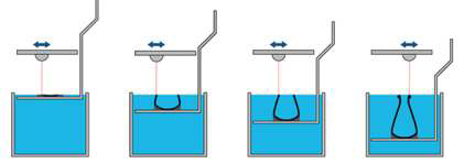 SLA printing has the advantage of being relatively fast. Parts can often be finished in one day or less, though part size is typically limited to 50 x 50 x 60 cm. This method is considered expensive, due to the cost of the photopolymer and the sophistication of the machines involved. The finished part is a solid plastic piece that can be machined or used as the master model for making a plastic injection molding die, for blow molding or other industrial processes. SLA is most often used for rapid prototyping and to test form, fit and function of new design ideas. The surface quality and precision of small features in SLA is considered excellent.
2. Selective Laser Sintering (SLS)
SLS is closely related to Direct Metal Laser Sintering (DMLS), so they will be discussed together. Both are examples of so-called “powder bed” methods. As with SLA above, the part will be divided into thousands of cross-sectional slices via a computer program. This program is then fed into the machine that will control the application of a fiber laser to sinter the material. Powder is introduced into the machine chamber on top of a build platform. The laser then draws the first layer of the design, sintering the powder into a solid. The build platform then descends the vertical distance of one layer’s thickness, typically in the range of 30~50μ. A wiper blade passes over the platform, depositing another layer of powder and the process is repeated until a finished part emerges
3. Fused Deposition Modeling (FDM)
Developed by S. Scott Crump in the late 1980s, this process was bought by Stratasys who had the exclusive right to this patented technology and the name by which it was described. That patent has since expired and many other players have now created a vibrant DIY community to develop new uses for 3D printers of this type, which has also consequently greatly reduced the cost.
This is the type of 3D printer that most laymen are now becoming familiar with. A spool of thermoforming plastic [hyperlink] or wire extrudes a supply of raw material to a dispensing nozzle. This nozzle will lay down successive layers of material onto a base platform, but unlike the other techniques mentioned above it is free to move in both the vertical and horizontal directions.
4. Selective Laser Melting (SLM)
Again a CAD drawing file is used to translate a three-dimensional object into a series of 2D layers that can be successively printed. Unlike with SLS, the granulated metal in this process is welded and not merely sintered, producing a part that is fully dense.
This process was invented in Germany in 1995. A high-powered laser is used, usually an ytterbium fiber laser. The metals that can be melted include cobalt chrome, tool steel, aluminum, stainless steel and titanium. All of the material must be finely and uniformly atomized, and the build takes place inside a sealed chamber filled with an inert gas such as argon. This is because powderized metals can be highly explosive if melted with a laser in normal atmospheric conditions.
5. Laminated Object Manufacturing (LOM)
Here a series of thin laminates are laid out on a build platform. The laminates can be paper, plastic sheet or metal foil. With each layer, a computer controlled laser or other cutting device traces out the pattern for that layer, cutting away that unwanted excess material. The platform then drops by the thickness of one layer, a new laminate is glued on top and the process continues. This stacking process makes a finished part which is less sophisticated than a SLS or SLM equivalent, but it is cheaper and does not require especially controlled working conditions. Also, if paper is used as the laminate the finished part will be similar to solid wood and can be worked accordingly.
6. Multi Jet Modeling (MJM)
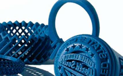 Another process developed by 3D Systems, this is something of a hybrid 3D printing device. As with SLA, a thermosetting polymer is used. But instead of having the finished part emerge from a bath of liquid material, an array of inkjet nozzles moves horizontally across the platform depositing a thin film for the 2D cross-sectional layer. Polymerization quickly solidifies the plastic in that layer, then the platform descends by one thickness and the process repeated.
7. Digital Light Processing (DLP)
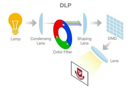 Another variation on the polymerization of a curable resin, this process is very similar to SLA printing. It cures the resin with a more conventional light source, but it also requires support structures and post-build curing. The process is generally faster and a more shallow reservoir of photoresin can be used which also saves on cost. Like with SLA, the finished part has excellent dimensional tolerances and surface finish.


