Courtesy: Arrow Electronics
Lithium-ion (Li-Ion) batteries are a common energy storage method for electric vehicles, offering very high energy density compared to all existing battery technologies. However, to maximize performance, it is essential to use a battery monitoring system (BMS) to safely manage the charging and discharging cycles, thereby extending the battery’s lifespan. This article will introduce the architecture and operation modes of BMS, as well as the product features and advantages of the BMS devices introduced by ADI.
BMS can enhance the operational efficiency of electric vehicle batteries
Advanced BMS can assist electric vehicles in efficiently extracting a significant amount of charge from the battery pack during operation. It can accurately measure the battery’s state of charge (SOC) to extend battery runtime or reduce weight, and enhance battery safety involves avoiding electrical overloads in the form of deep discharge, overcharging, overcurrent, and thermal overstress.
The primary function of the BMS is to monitor the physical parameters during battery operation, ensuring that each individual cell within the battery pack stays within its safe operating area (SOA). It monitors the charging and discharging currents, individual cell voltages, and the overall battery pack temperature. Based on these values, it not only ensures the safe operation of the battery but also facilitates SOC and state of health (SOH) calculations.
Another crucial function provided by the BMS is cell balancing. In a battery pack, individual cells may be connected in parallel or series to achieve the desired capacity and operating voltage (up to 1 kV or higher). Battery manufacturers attempt to provide identical cells for the battery pack, but achieving perfect uniformity is not physically realistic. Even small differences can lead to variations in charging or discharging levels, and the weakest cell in the battery pack can significantly impact the overall performance. Precise cell balancing is a vital feature of the BMS, ensuring the safe operation of the battery system at its maximum capacity.
Wireless BMS removes communication wiring, reducing complexity
Electric vehicle batteries are composed of several cells connected in series. A typical battery pack, with 96 cells in series, generates over 400 V when charged at 4.2 V. The more cells in the battery pack, the higher the voltage achieved. While the charging and discharging currents are the same for all cells, it is necessary to monitor the voltage on each cell.
To accommodate the large number of batteries required for high-power automotive systems, multiple battery cells are often divided into several modules and distributed throughout the entire available space in the vehicle. A typical module consists of 10 to 24 cells and can be assembled in different configurations to fit various vehicle platforms. Modular design serves as the foundation for large battery packs, allowing the battery pack to be distributed over a larger area, thus optimizing space utilization more effectively.
In order to support a distributed modular topology in the high EMI environment of electric/hybrid vehicles, a robust communication system is essential. Isolated CAN bus is suitable for interconnecting modules in this environment. While the CAN bus provides a comprehensive network for interconnecting battery modules in automotive applications, it requires many additional components, leading to increased costs and circuit board space. Moreover, if modern Battery Management Systems (BMS) adopt wired connections, it comes with significant drawbacks. Wiring becomes a challenging issue as wires need to be routed to different modules, adding weight and complexity. Wires are also prone to pick up noise, requiring additional filtering.
Wireless BMS is a novel architecture that eliminates the need for communication wiring. In a wireless BMS, interconnection between each module is achieved through wireless connections. The wireless connection in large battery packs with multiple cells reduces wiring complexity, lowers weight, decreases costs, and enhances safety and reliability. However, wireless communication faces challenges in harsh EMI environments and signal propagation obstacles caused by RF-shielding metal components.
Embedded wireless networks can improve reliability and precision
The SmartMesh embedded wireless network, introduced by ADI, has undergone on-site validation in Industrial Internet of Things (IoT) applications. It achieves redundancy through the use of path and frequency diversity, providing connections with reliability exceeding 99.999% in challenging environments such as industrial and automotive settings.
In addition to enhancing reliability by creating multiple redundant connection points, wireless mesh networks also extend the functionalities of BMS. The SmartMesh wireless network enables flexible placement of battery modules and improves the calculation of battery SOC and SOH. This is achieved by collecting more data from sensors installed in locations previously unsuitable for wiring. SmartMesh also provides time-correlated measurement results from each node, enabling more precise data collection.
ADI has integrated the LTC6811 battery stack monitor with ADI SmartMesh network technology, representing a significant breakthrough. This integration holds the potential to enhance the reliability of large multi-cell battery packs in electric and hybrid vehicles while reducing costs, weight, and wiring complexity.
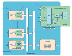
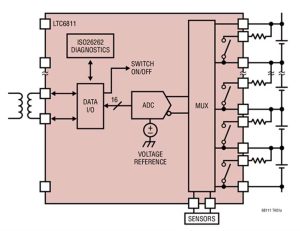
The LTC6811 is a battery stack monitor designed for multi-cell battery applications. It can measure the voltage of up to 12 series-connected cells with a total measurement error of less than 1.2mV. The measurement of all 12 cells can be completed within 290μs, and a lower data acquisition rate can be selected for high noise reduction. The LTC6811 has a battery measurement range of 0V to 5V, suitable for most battery chemistry applications. Multiple devices can be daisy-chained to simultaneously monitor very long high-voltage battery stacks. The device includes passive balancing for each cell, and data exchange occurs on either side of an isolation barrier, compiled by the system controller. The controller is responsible for calculating SOC, controlling battery balancing, checking SOH, and ensuring the entire system stays within safe limits.
Moreover, multiple LTC6811 devices can be daisy-chained, allowing simultaneous monitoring of long high-voltage battery stacks. Each LTC6811 has an isoSPI interface for high-speed and RF-resistant remote communication. When using LTC6811-1, multiple devices are connected in a daisy-chain, and all devices share one host processor connection. When using LTC6811-2, multiple devices are connected in parallel to the host processor, and each device is individually addressed.
The LTC6811 can be powered directly from the battery pack or an isolated power source and features passive balancing for each battery cell, along with individual PWM duty cycle control for each cell. Other features include a built-in 5V regulator, 5 general-purpose I/O lines, and a sleep mode (where current consumption is reduced to 4μA).
Cell balancing is employed to optimize battery capacity and performance
Cell balancing has a significant impact on the performance of batteries because even with precise manufacturing and selection, subtle differences can emerge between them. Any capacity mismatch between cells can lead to a reduction in the overall capacity of the battery pack. Clearly, the weakest cell in the stack will dominate the performance of the entire battery pack. Cell balancing is a technique that helps overcome this issue by equalizing the voltage and SOC between cells when the battery is fully charged.
Cell balancing technology can be divided into passive and active types. When using passive balancing, if one cell is overcharged, the excess charge is dissipated into a resistor. Typically, a shunt circuit is employed, consisting of a resistor and a power MOSFET used as a switch. When the cell is overcharged, the MOSFET is closed, dissipating the excess energy into the resistor. LTC6811 uses a built-in MOSFET to control the charging current for each monitored cell, thus balancing each cell being monitored. The integrated MOSFET allows for a compact design and can meet a 60 mA current requirement. For higher charging currents, an external MOSFET can be used. The device also provides a timer to adjust the balancing time.
On the other hand, active balancing involves redistributing excess energy among other cells in the module. This approach allows for energy recovery and lower heat generation, but the disadvantage is that it requires a more complex hardware design.
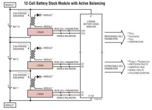
ADI has introduced an architecture using LT8584 to achieve active balancing of batteries. This architecture actively shunts charging current and returns energy to the battery pack, addressing the issues associated with passive shunt balancers. Energy is not dissipated as heat but is instead reused to recharge the remaining batteries in the stack. The architecture of this device also tackles a problem where one or more cells in the stack reach a low safe voltage threshold before the entire stack’s capacity is depleted, resulting in reduced runtime. Only active balancing can redistribute charge from stronger cells to weaker ones, allowing weaker cells to continue supplying power to the load and extracting a higher percentage of energy from the battery pack. The flyback topology enables charge to move back and forth between any two points in the battery pack. In most applications, the charge is returned to the battery module (12 cells or more), while in other applications, the charge is returned to the entire battery stack or auxiliary power rails.
The LT8584 is a monolithic flyback DC/DC converter designed specifically for active balancing of high-voltage battery packs. The high efficiency of the switch-mode regulator significantly increases the achievable balancing current while reducing heat dissipation. Additionally, active balancing allows for capacity recovery in stacks of mismatched batteries, a feature not attainable with passive balancing systems. In typical systems, over 99% of the total battery capacity can be achieved.
The LT8584 features an integrated 6A, 50V power switch, reducing the design complexity of the application circuit. The device operates entirely relying on the cells which it is discharging, eliminating the need for complex biasing schemes typically required when using an external power switches. The enable pin (DIN) is designed to seamlessly coordinate with the LTC680x series battery stack monitor ICs. Additionally, when used in conjunction with LTC680x series devices, the LT8584 provides system telemetry functions, including current and temperature monitoring. When disabled, the LT8584 typically consumes less than 20nA of total static current from the battery.
Conclusion
The key to low-emission vehicles lies in electrification, but it also requires smart management of energy sources (such as lithium-ion batteries). Improper management could render the battery pack unreliable, significantly reducing the safety of the vehicle. Both active and passive battery balancing contribute to safe and efficient battery management. Distributed battery modules are easy to support, and they can reliably transmit data to the BMS controller, whether through wired or wireless means, enabling dependable SOC and SOH calculations. ADI offers a comprehensive range of BMS components that can assist customers in accelerating BMS development, ensuring more efficient management of the operational efficiency and safety of electric vehicle batteries.


