


In the application of flyback topology power supply, the drain-source voltage of MOSFET may exceed the rated value under certain extreme conditions. Engineers prefer to choose MOSFET with higher voltage endurance to increase its margin. When the drain-source voltage of MOSFET exceeds the rated value, the MOSFET will have an avalanche breakdown; the avalanche current IAR and avalanche energy EAS will be the key parameters to measure the avalanche capability of MOSFET.


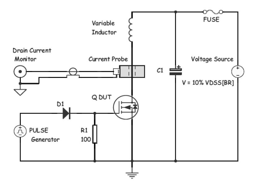
- EAS test circuit
EAS= LI2() Formula 1
VAV: avalanche voltage VBUS : Voltage of the voltage source for avalanche testing.
Because VBUS is far lower than VAV, the Formula 1 is approximately equal to below Formula 2:
EAS= LI2 Formula 2
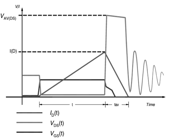
The temperature of MOSFET will rise because of avalanche breakdown. If the junction temperature caused by the avalanche exceed 150℃, MOSFET will fail because of overheat.
- The EAS in the specification
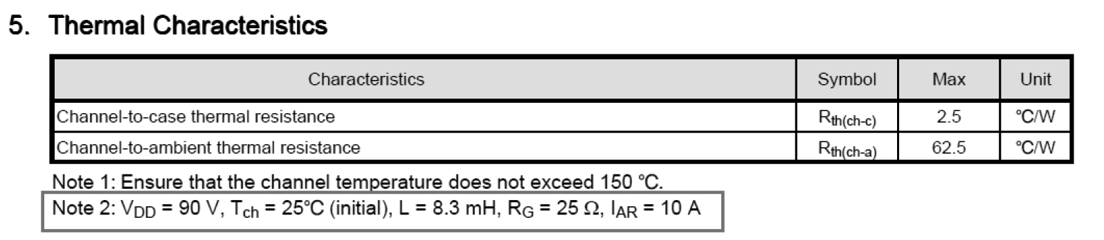
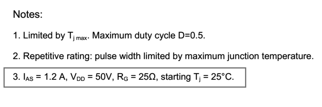
The EAS in the specification is tested with defined test condition, e.g.:
Table 1 **10A80E Specification Excerpt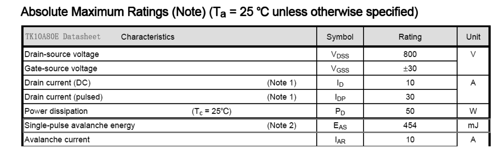
EAS value of **10A80E is consistent with the specification if calculated as Formula 2.
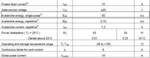
Table 2 ***60R580P Specification Excerpt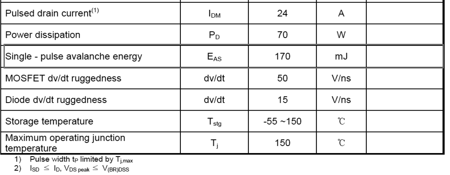
However, for the EAS parameters of ***60R580P, the test condition is not mentioned on datasheet. EAS has necessary connections with inductance as well as avalanche current. There is no comparision between EAS of different MOSFETs based on different test conditions.
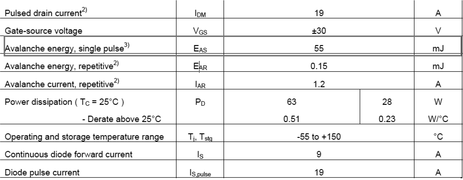
- Table 3 CYG WAYON WMO11N60C2 specification Excerpt
The EAS test condition of CYG WAYON WMO11N65C2 is clearly mentioned in the specification.
- Test validation
Based on the same test condition on table 3, increasing the IAS to 2.3A, the EAS of WMO11N65C2 is 206mJ, which is higher than 179mJ calculated EAS value of ***60R580P.
- CYG WAYON WMO11N65C2 EAS Limitation Test
10pcs test data of ultimate avalanche energy value:
| P/N:
WMO11N60C2 |
EAS Max (mJ) | |||||||||
| 1 | 2 | 3 | 4 | 5 | 6 | 7 | 8 | 9 | 10 | |
| 305.76 | 305.76 | 327.99 | 305.76 | 305.76 | 327.99 | 305.76 | 327.99 | 305.76 | 327.99 | |
- EAS Margin for power supply
In the practical applications of Flyback power supply, the leakage inductance is about 3% of the total inductance.
E.g.: output power: 75W; switching frequency:60KHZ; E36 magnetic core; the primary winding: N67.
Primary inductance: Lprimary = 557 mH;
Primary leakage inductance: Lleakage = 0,03 × Lprimary = 16.71 μH;
Primary input voltage: VBus = (265Vrms ×) – VDiode = 372V
Primary VReset: = 100 V
VDS(Flyback) = VBus + VReset = 472 V, referring to use 600V MOSFET, meet the requirement of 0.8 times margin;
The switching cycles of MOFET: T=16.667 μs; Duty Cycle: D=0.2
MOSFET tON=D*T=3.517 μs
ID(Peak) =*tON=2.348 A
Considering some extreme input conditions, ID(Peak)=5A; EAS=LI2=0.5*0.557mH*25=6.96mJ;(above calculations are based on 75W power supply)
In 45W power supply, ID is smaller, more EAS margin is there.