
Key takeaways:
- Oscilloscopes are primarily time-domain measurement instruments that mostly display timing-related characteristics.
- However, mixed-domain oscilloscopes give you the best of both worlds by including built-in spectrum analyzers for frequency-domain measurements.
- Modern oscilloscopes sport extremely sophisticated triggering and analysis features, both on-device and through remote measurement software.
After a multimeter, an oscilloscope is probably the second-most popular instrument on an engineer’s workbench. Oscilloscopes enable you to peer into the internals of electronic devices and monitor the signals they use under the hood.
What do engineers look for when using oscilloscopes? What are some innovations that these instruments have facilitated? What are some key characteristics to look for? Find out the answers to all this and more below.
What is the primary function of oscilloscopes in electronic measurements?
Oscilloscopes enable engineers to measure and visualize the amplitude of an electrical signal over time. This is also the reason they are generally considered time-domain measurement instruments. However, there are mixed-domain oscilloscopes that provide both time-domain (amplitude vs. time) and frequency-domain (power vs. frequency) measurements.
The precise characterization of waveforms is a critical diagnostic tool in every stage of an electronic product lifecycle, including cutting-edge research, prototyping, design, quality assurance, compliance, maintenance, and calibration.
Let’s look at the type of signals that are being tested with oscilloscopes in various industries to facilitate innovations and products.
What signal characteristics are verified using oscilloscopes?
When experienced electronics engineers are troubleshooting issues using oscilloscopes, they are looking for evidence of several ideal characteristics as well as problematic phenomena, depending on the type of signal and the application. Some of the common aspects and phenomena they examine are listed below:
- Signal shape: The waveform should match the expected shape if the specification requires a square, sawtooth, or sine wave. Any deviations might indicate an issue.
- Amplitude: The signal levels should remain within the expected range of volts without excessive fluctuations.
- Frequency or period: The frequency or period of the signal should always remain within specified limits. Deviations from the expected frequency can lead to synchronization problems in communication and control systems.
- Rise and fall times: For digital signals, sharp and consistent rise and fall times are essential for reliable operation. If the rise time is slower than required, it may lead to problems like data corruption, timing errors, and reduced performance in digital circuits. If it’s overly fast, it can lead to increased electromagnetic interference as well as signal integrity issues like ringing and crosstalk.
- Jitter: Jitter is the variation in a signal characteristic during significant transitions. Period jitter is the variation in the duration of individual clock periods. Cycle-to-cycle jitter is the variation in duration between consecutive clock cycles. Phase jitter is the variation in the phase of the signal with respect to a reference clock. Timing jitter is the variation in the timing of signal edges. Low jitter indicates stable signal timing. Excessive jitter may cause errors in high-speed digital communication.
- Phase consistency: In systems with multiple signals, phase consistency between them is critical for proper synchronization.
- Duty cycle: For pulse-width modulation signals and clock signals, the duty cycle should be as specified.
- Noise: Noise is any unwanted disturbance that affects a signal’s amplitude, phase, frequency, or other characteristics. It should be minimal and within acceptable limits to avoid interference and degradation of the signal. Too much noise indicates poor signal integrity, possible shielding issues, or noise due to suboptimal power supply. Phase noise can affect the synchronization of communication and clock signals.
- Harmonics and distortion: For analog signals, low harmonic distortion ensures signal fidelity.
- Ringing: Ringing refers to oscillations after a signal transition, usually seen in digital circuits, that can lead to errors and signal integrity issues.
- Crosstalk: Unwanted coupling from adjacent signal lines can appear as unexpected waveforms on the oscilloscope trace.
- Drift: Changes in signal amplitude or frequency over time are indicators of instability in the power supply or other components.
- Ground bounce: Variability in the ground potential, often visible as a noisy baseline, can be critical in fast-switching digital circuits.
- Clipping: If the input signal amplitude exceeds the oscilloscope’s input range, the displayed waveform will be clipped, indicating a need for signal attenuation or a more appropriate input setting on the scope.
- Direct current (DC) offsets: Unexpected DC offsets can indicate issues with the waveform generation or coupling methods.
- Aliasing: Aliasing occurs if the oscilloscope sampling rate is too low for the signal frequency, leading to an incorrect representation of the signal.
What types of waveforms and signals can be analyzed using an oscilloscope?
Oscilloscopes are used to verify a variety of analog signals and digital signals in many industries as explained below.
5G and 6G telecom
The radio frequency (RF) signals used in telecom systems and devices must strictly adhere to specifications for optimum performance as well as regulatory compliance.
Some examples of oscilloscope use in this domain include:
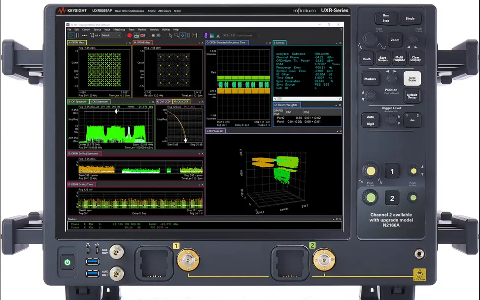
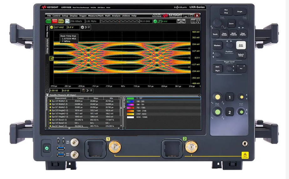
- InfiniiumUXR-B series real-time oscilloscopes (RTOs) for characterizing 5G and 6G systems, including phased-array antenna transceivers and mmWave wideband analysis capable of measuring frequencies as high as 110 gigahertz (GHz) and bandwidths of as much as 5 GHz
- development and verification of 41-GHz power amplifier chips for 5G New Radio applications
- qualifying a 6G 100 gigabits-per-second (Gbps) 300GHz (sub-terahertz) wireless data link using a 70 GHz UXR0704B Infiniium UXR-Series RTO
Photonics and fiber optics
Oscilloscopes are extensively employed for functional and compliance testing of optical and electrical transceivers used in high-speed data center networks.
Some of the use cases are listed below:
- Oscilloscopes, with the help of optical-to-electrical adaptors, verify characteristics like phase-amplitude modulation (PAM4) of 400Ghigh-speed optical networks.
- Oscilloscopes test the conformance of 400G/800G electrical data center transceivers with the Institute of Electrical and Electronics Engineers (IEEE) 802.3CK and the Optical Internetworking Forum’s (OIF) OIF-CEI-5.0 specifications.
- Real-time oscilloscopes like the UXR-B are used to evaluate the forward error correction performance of high-speed optical network links.
Digital interfaces of consumer electronics
Oscilloscopes and arbitrary waveform generators are used together for debugging and automated testing of high-speed digital interfaces like:
- Wi-Fi 7 networking standard
- universal serial bus (USB)
- mobile industry processor interface (MIPI) standards
- peripheral component interconnect express (PCIe) buses
- high-definition multimedia interface (HDMI)
They are also being used for testing general-purpose digital interfaces like the inter-integrated circuit (I2C), the serial peripheral interface (SPI), and more.
Automotive radars and in-vehicle networks
Oscilloscopes are used for validating automotive mmWave radar chips. Additionally, oscilloscopes are extensively used for verifying automotive in-vehicle network signals like:
- automotive Ethernet
- controller area network (CAN)
- FlexRay
- local interconnect network (LIN)
Aerospace and defense
Radars for aerospace and defense uses are validated using instruments like the UXR-series oscilloscopes.
They are also used for ensuring that data communications comply with standards like the MIL-STD 1553 and ARINC 429.
Space
Oscilloscopes are being used for developing 2.65 Gbps high-speed data links to satellites.
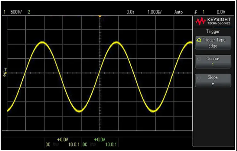
How does an oscilloscope visually represent electrical signals?
An oscilloscope’s display panel consists of a two-dimensional resizable digital grid. The horizontal X-axis represents the time base for the signal, while the vertical Y-axis represents signal amplitude in volts.
Each segment of an axis is called a division (or div). Control knobs on the oscilloscope allow the user to change the magnitude of volts or time that each div represents.
Increasing this magnitude on the X-axis means more seconds or milliseconds per division. So you can view a longer capture of the signal, effectively zooming out on it. Similarly, by reducing the magnitude on the X-axis, you’re able to zoom into the signal to see finer details. The maximum zoom depends on the oscilloscope’s sampling rate. It’s often possible to zoom in to nanosecond levels on modern oscilloscopes since they have sampling rates of some giga samples per second.
Similarly, you can zoom in or out on the Y-axis to examine finer details of changes in amplitude.
What are the various types of oscilloscopes?
Some of the common types of oscilloscopes are:
- Digital storage oscilloscopes (DSOs): They capture and store digital representations of analog signals, allowing for detailed analysis and post-processing. All modern scopes, including the sub-types below, are DSOs. The term differentiates them from older analog scopes that showed waveforms by firing an electron beam from a cathode ray tube (CRT) onto a phosphor-coated screen to make it glow.
- Mixed-signal oscilloscopes (MSOs): They integrate both analog and digital channels, enabling simultaneous observation of analog signals and digital logic states. They’re useful for use cases like monitoring power management chips.
- Mixed-domain oscilloscopes (MDOs): They combine normal time-domain oscilloscope functions with a built-in spectrum analyzer, allowing for time-correlated viewing of time-domain and frequency-domain signals.
- Real-time oscilloscopes: They capture and process a waveform in real time as it happens, making them suitable for non-repetitive and transient signal analysis.
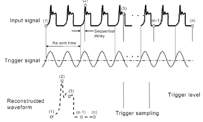
- Equivalent time oscilloscopes: Equivalent time or sampling oscilloscopes are designed to capture high-frequency or fast repetitive signals by reconstructing them using equivalent time sampling. They sample a repetitive input signal at a slightly different point of time during each repetition. By piecing these samples together, they can reconstruct an accurate representation of the waveform, even one that is very high frequency.
How does an oscilloscope differ from other test and measurement equipment?
Oscilloscopes often complement other instruments like spectrum analyzers and logic analyzers. Some key differences between oscilloscopes and spectrum analyzers include:
- Purpose: Oscilloscopes show how a signal changes over time by measuring its amplitude. Spectrum analyzers show how the energy of a signal is spread over different frequencies by measuring the power at each frequency.
- Displayed information: Oscilloscopes show time-related information like rise and fall times, phase shifts, and jitter. Spectrum analyzers show frequency-related information like signal bandwidth, carrier frequency, and harmonics.
- Uses: Oscilloscopes are extensively used for visualizing signals in real time and near real time. Spectrum analyzers are useful when frequency analysis is critical, such as in radio frequency communications and electromagnetic interference testing.
A mixed-domain oscilloscope combines oscilloscope and spectrum analyzer capabilities in a single instrument with features like fast Fourier transforms (FFT) to convert between the two domains.
Another complementary instrument is a logic analyzer. Both mixed-signal oscilloscopes and logic analyzers are capable of measuring digital signals. But they differ in some important aspects:
- Analog and digital signals: An MSO can measure both analog and digital signals. However, logic analyzers only measure digital signals.
- Number of channels: Most oscilloscopes support two to four channels and a few top out around eight. In sharp contrast, logic analyzers can support dozens to hundreds of digital signals.
- Analysis capabilities: Oscilloscopes provide sophisticated triggering options for capturing complex analog signals. But logic analyzers can keep it relatively simple since they only focus on digital signals.
What are the key specifications to consider when choosing an oscilloscope for a specific application?
The most important specifications and features to consider when choosing an oscilloscope include:
- Bandwidth: For analog signals, the recommended bandwidth is three times or more of the highest sine wave frequency. For digital signals, the ideal bandwidth is five times or more of the highest digital clock rate, measured in hertz (Hz), megahertz (MHz), or GHz.
- Sample rate: This is the number of times the oscilloscope measures the signal each second. State-of-the-art oscilloscopes, like the UXR series, support up to 256 giga samples (billion samples) per second, which works out to a measurement taken every four femtoseconds. The sample rate dramatically impacts the signal you see on the display. An incorrect sample rate can result in an inaccurate or distorted representation of a signal. A low sample rate can cause errors to go undetected because they can occur between collected samples. The sample rate should be at least twice the highest frequency of the signal to avoid aliasing, but a sample rate of 4-5 times the bandwidth is often recommended to precisely capture signal details.
- Waveform update rate: A higher waveform rate increases the chances of detecting possible glitches and other infrequent events that occur during the blind time between two acquisitions.
- Number of channels: Most use cases are mixed-signal environments with multiple analog and digital signals. Select an oscilloscope with sufficient channels for critical time-correlated measurements across multiple waveforms.
- Effective number of bits (ENOB): ENOB says how many bits are truly useful for accurate measurements. Unlike the total analog-to-digital converter (ADC) bits, which can include some bits influenced by noise and errors, ENOB reflects the realistic performance and quality of the oscilloscope’s measurements.
- Signal-to-noise ratio (SNR): This is the ratio of actual signal information to noise in a measurement. Low SNR is recommended for higher accuracy.
- Time base accuracy: This tells you the timing accuracy in parts per billion.
- Memory depth: This is specified as the number of data points that the scope can store in memory. It determines the longest waveforms that can be captured while measuring at the maximum sample rate.
What trends are emerging in oscilloscope development?
Some emerging trends in oscilloscopes and onboard embedded software are in the areas of signal analysis, automated compliance testing, and protocol decoding capabilities:
Advances in signal analysis include:
- deep signal integrity analysis for high-speed digital applications
- advanced statistical analysis of jitter and noise in digital interfaces in the voltage and time domains
- analysis of high-speed PAM data signals
- power integrity analysis to understand the effects of alternating or digital signals and DC supplies on each other
- de-embedding of cables, probes, fixtures, and S-parameters to remove their impacts from measurements for higher accuracy
Automated compliance testing software can automatically check high-speed digital transceivers for compliance with the latest digital interface standards like USB4, MIPI, HDMI, PCIe 7.0, and more.
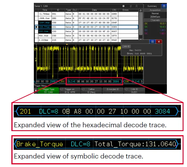
Comprehensive protocol decoding capabilities enable engineers to understand the digital data of MIPI, USB, automotive protocols, and more in real time.
Measure with the assurance of Keysight oscilloscopes
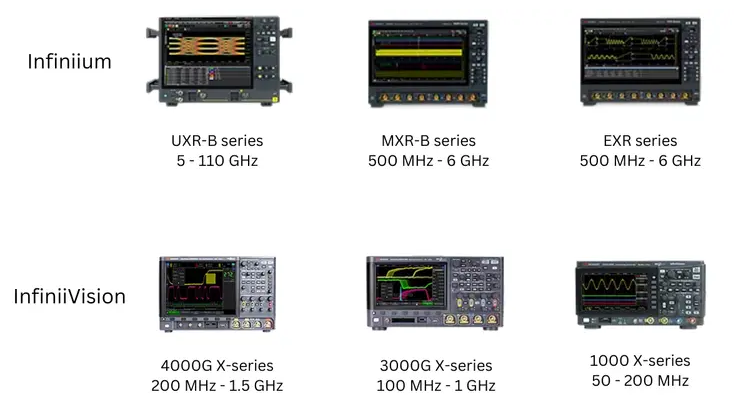
This blog introduced several high-level aspects of oscilloscopes. Keysight provides a wide range of state-of-the-art, reliable, and proven oscilloscopes including real-time and equivalent-time scopes for lab use and handheld portable oscilloscopes for field use.

Product Marketing
Keysight Technologies